fitz43
Veteran and General Yakker
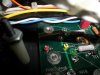
but those 100 volt DC pads are close enough to the edge as it is and then have that distance lees AND then the board touching the chassis doesn't seem like a long term, trouble free option....
Need more nomex paper?

but those 100 volt DC pads are close enough to the edge as it is and then have that distance lees AND then the board touching the chassis doesn't seem like a long term, trouble free option....
Need more nomex paper?
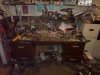
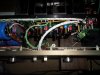
The aftermath...