You are using an out of date browser. It may not display this or other websites correctly.
You should upgrade or use an alternative browser.
You should upgrade or use an alternative browser.
PL700 Rebuild
- Thread starter Overundr1
- Start date
Sunnbobb
Journeyman
Signal from source is clean?
mlucitt
Veteran and General Yakker
I would put my ungrounded scope on the outputs to see the distortion, then work backwards along the signal path until I found no distortion. If this issue is present on both channels, it is likely a power problem. Ensure the rail fuses are all good by verifying the voltage on the load side of each rail fuse.
Good luck hunting.
Good luck hunting.
Overundr1
Journeyman
- Joined
- Sep 12, 2024
- Messages
- 195
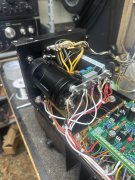
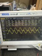
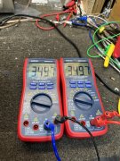
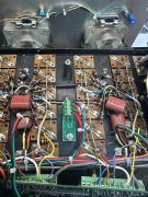
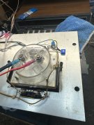
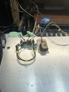
Wife out of hospital and on the mend so back at it. New triac board installed, trimmer for led’s installed, new turret board installed. Still have output distortion. Bias still perfect about 1mv of offset. All fuse holders cleaned and correct agx fuses installed. VU meters respond correctly. Hooked up my scope and what in flouroscanland is this? No input and look at the double waveform (one probe). Duplicated on my old Techtronix as well. Have my suspicions but rather than guess thought I would ask for suggestions. Also have rca predrivers in all four bottom row locations.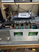


Bob Boyer
Veteran and General Yakker
Glad your wife is out of the hospital. Hope she's on the mend and can enjoy Thanksgiving. Been there, done this with one or the other of us. It's always tough, even as there is much for which to be thankful.
Good luck tracing this down, too. I'm watching from afar.
Good luck tracing this down, too. I'm watching from afar.
From your picture, it appears that you may have the ground channel to channel jumper in place on the board backside between pad 5L1 and 5R1. Cannot tell for sure but it appears that way in your photo. When you added the wires to the single point ground bus bar to terminal block 5R and 5L, that jumper was to be removed to prevent inadvertent ground looping.Wife out of hospital and on the mend so back at it. New triac board installed, trimmer for led’s installed, new turret board installed. Still have output distortion. Bias still perfect about 1mv of offset. All fuse holders cleaned and correct agx fuses installed. VU meters respond correctly. Hooked up my scope and what in flouroscanland is this? No input and look at the double waveform (one probe). Duplicated on my old Techtronix as well. Have my suspicions but rather than guess thought I would ask for suggestions. Also have rca predrivers in all four bottom row locations.View attachment 84378View attachment 84379View attachment 84380View attachment 84381View attachment 84382View attachment 84383
Overundr1
Journeyman
- Joined
- Sep 12, 2024
- Messages
- 195
Almost like any real input level increase triggers the distortion. At ultra low levels amounts perfect. Out of time for scope work today will dig in again tomorrow. Did test on known good speakers just for my own sanity.
May have to inject signal directly into the board input point and start chasing the trace
May have to inject signal directly into the board input point and start chasing the trace
Bob Boyer
Veteran and General Yakker
I found out just how fast a sepsis attack can affect us retired folks. In the space of two hours she went from I don’t feel so good to collapse and ambulance call. Thanks for the well wishes
Oh my. Been down that path. About lost Pat to sepsis last year when they postponed surgery for two hours to wait until the morning. Two hours is all it takes. My thoughts are with you guys.
Overundr1
Journeyman
- Joined
- Sep 12, 2024
- Messages
- 195
First off the fact that Joe includes the schematic for his proprietary board makes trouble shooting so much easier, thank you sir. Verified clean signal generator input to rca jacks, input to control board clean, input both inverting and non inverting pins 2 and 3 on the op amp clean, pin 7 15.1v pin 4 -15.1v. However output on pin 6 was a disaster on either channel, wish I could hold phone oscope probe and take a picture all at the same time. basically a lot of hash and minimal waveform. anyways need to order some op134's.
Can only blame myself, even with checking followed the wrong back plane output transistor numbering sequence and probably stressed those poor op amps by doing so even on a dbt startup. Stay tuned for the next installment once Mouser gets me the op amps.
Can only blame myself, even with checking followed the wrong back plane output transistor numbering sequence and probably stressed those poor op amps by doing so even on a dbt startup. Stay tuned for the next installment once Mouser gets me the op amps.

