PL400 glad I found this forum.

wattsabundant

Chief Journeyman
Joined
Apr 26, 2011
Messages
932
Location
Central Ohio
#61
I don't see a fuse on the fan. Those heaters can get quite hot and possibly melt the the AC wiring. I don't think the box is big enough for extended testing.

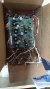
Attached are photos of a loadbank I built for testing inverters at the day job. The wiring is transformer magnet wire with high temp sleeving. The heaters are 1000 watt/120 volt which works out to 13 ohms. There are 660 watt heaters AT 21 OHMS. A 660 watt and a 1000 watt heat cone in parallel would equal be very close to 8 ohms. Used for testing amps they would be ok. Here is a 660 watt version. EBAY heat cone.

Of course a person cou always look for the Dale 8 ohm resistors on EBAY and pay the price.
 

Attachments

Joined
Apr 28, 2023
Messages
116
Location
South Central VA.
Tagline
X usaf electronic tech.
#62
Return that thing to toaster duty and get a proper one. :)
Hey it may have had a formal life as something else but it wasn't a toaster ,speed control resistor for old wound rotor motor took awhile to find a 10 ohm one. Conducts current just as well even does air frying on the side
 
Joined
Apr 28, 2023
Messages
116
Location
South Central VA.
Tagline
X usaf electronic tech.
#63
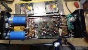
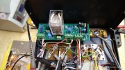
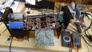
Getting close to finish line got my" watts relay " looked at pictures off and away. All done just waiting for input rca post. Relay board fits in really nice had everything I needed to do my job. My meters feed from output post so I teamed them together in terminal.
I assume the .01 ohm resistor between neg output post and isolated ground pad for input commons is no longer needed? Also those RC circuits on output post no longer needed also?

Thanks Don beautiful work.
 

wattsabundant

Chief Journeyman
Joined
Apr 26, 2011
Messages
932
Location
Central Ohio
#66
The original R/C networks are removed along with the original output binding posts. The relay board mounts on the new output binding posts. As Lee said the new R/C network is on the board. The resistor between binding post and input jacks is cut out, at the body of the resistor. This leaves a stab on the input bus bar to solder on the ground wire. The unterminated white wire in the photo lands on the bus bar stab.

Changing out all of those caps on the driver board had to be a lot of tedious work. Hats off to you if you managed to pull that off without damaging the board.
 
Joined
Apr 28, 2023
Messages
116
Location
South Central VA.
Tagline
X usaf electronic tech.
#67
Changing out all of those caps on the driver board had to be a lot of tedious work. Hats off to you if you managed to pull that off without damaging the board.
Lets put it this way someone beat me to beating up the board I only added one place of damage but one eye lifted when i sucked solder 1972 board lol.
Thanks Don
 
Joined
Apr 28, 2023
Messages
116
Location
South Central VA.
Tagline
X usaf electronic tech.
#68
Well my attempt at figuring out right channel protection circuit went from cutting the circuit off to distorted signal over 8K hz. So I lifted D9,D10 again both channels working however at 20K sign wave turns sawtooth seems to run away but as that happens my wattsr opens up great job.
All above test were with DB @88vac to unit .
Advice as too either problem?
I just replaced Q8,Q9 rechecked diodes stumped. I am getting frustrated at this CP circuit issues.
 

WOPL Sniffer

Veteran and General Yakker
Joined
Aug 10, 2015
Messages
11,522
Location
Minnie-Soda
Tagline
Screw it
#69
Well my attempt at figuring out right channel protection circuit went from cutting the circuit off to distorted signal over 8K hz. So I lifted D9,D10 again both channels working however at 20K sign wave turns sawtooth seems to run away but as that happens my wattsr opens up great job.
All above test were with DB @88vac to unit .
Advice as too either problem?
I just replaced Q8,Q9 rechecked diodes stumped. I am getting frustrated at this CP circuit issues.


Marvin1.jpg
 
Joined
Apr 28, 2023
Messages
116
Location
South Central VA.
Tagline
X usaf electronic tech.
#71
I guess I need sockets on my D9,10 lol.
Is there an answer on the high freq issue im having . Any suggestions I'm willing to try anything, it runs strong till I get up to 20k .
Changes I have done From reading ; with my outputs came 4 ea 33pf caps with instructions to put on base- collector on Q7,10 for oscillations.
Also I install 470uf with the opposing diodes C6 .
I'm thinking of removing would that be the right direction for my high freq issue?.
Also should I be able to run all test using DB before going full voltage ?
 
Joined
Apr 28, 2023
Messages
116
Location
South Central VA.
Tagline
X usaf electronic tech.
#74
So then your saying the series one or pl14 board cant predrive mjxx xx drivers but the series 2 pl36 board can ?
I guess I'm just saying this set I bought as a matched set was for a series 2 I guess.

But I still have the problem with right protection circuit distorted starting at 8khz.

Ok so I have a complete set 410,909s I will install.

So my MJ 21196 will oscillate high freq ok bummer. IMG_20230520_155839750.jpg
 

gene french

Veteran and General Yakker
Joined
Mar 6, 2022
Messages
5,555
Location
guayabo de bagaces, guanacaste, costa rica....
Tagline
music...the healer of souls...
#76
i have a set of the MJ 21196 i bought in case i needed to change them all....so far i have not had to use them...
but, i was warned to use the 410s or the 66546 (rebranded 410) or the sj2741s as drivers....
mr. joe sold them to me...mr laatsch verified along with mr mark...these were good quasi subs for the f pl909 and xpl 909...
i guess i need to sub one out to test for myself...
i just kinda bought them for spares or if marvin visited while refurbishing these...
somebody please jump in if i am misinformed...
 

George S.

Veteran and General Yakker
Joined
Feb 18, 2020
Messages
5,021
#77
Yup the was my understanding, the DRIVERS. Joe explained this once saying only two are needed. I'll see if I can find it
 

gene french

Veteran and General Yakker
Joined
Mar 6, 2022
Messages
5,555
Location
guayabo de bagaces, guanacaste, costa rica....
Tagline
music...the healer of souls...
#79
Yup the was my understanding, the DRIVERS. Joe explained this once saying only two are needed. I'll see if I can find it
column 2 and 4 have to be drivers....1 and 3 can be the outputs...column 1 being nearest to the transformer...
this i did do once on my 400c driver board...it stayed that way until i completely upgraded to wopl...
ran almost a year in that configuration...mr. joe was a ton of help on that episode...
 
Top