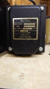
we have the same meter. nice speaker relay.
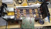
my right channel works like a dream bias easily adjust to 350 r20 about mid pot.
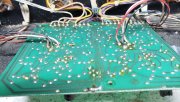
Left however i found a few shorted diodes replaced checked Qs even Q6 (2n1305) is a strange lead config laying flat ECB put in my tester reads 420, old one 1303 reads 352 . at least i have no dc on output left

( right channel has 37mvdc.
I ordered new 410 drivers to replace 2 bad ones from set i removed so i will have good set of 410,xpl909s as back up if needed.
right now im running a set of matched MJ21196G,MJ15042G .
Thanks Gene for hanging in there with me.
im getting closer to order wo board forget this 14a. but im gonna keep plugging away till i find my issue.
FYI i did rework all the wires notice broken strands on most so cut off tips stripped and tinned reattached.
When i First fired her up with the high dc output on left i checked my bias it was like 542mv not adjustable.
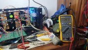
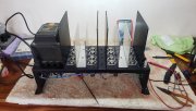
Question while troubleshooting this issue should i leave the bulb unit hooked up or go to full voltage i feel like leaving it hooked up with reduced voltage 94vac at bridge input.
also I lifted a lead from D9 D10 to take out protection circuit has same problem no change.
leave the dim bulb tester on while trouble shooting...it will save your butt....
when you set the bias for the final time....it must be done on shore power and not the dim bulb tester...
your rail voltage will be low...as you mentioned the ac is low too....
the dbtester with a 100 watt bulb will restrict your current to about 1 amp....well below the 5 amp rail fuses....
if the dbtester is dimming....you can almost be guaranteed the outputs are not shorted....
and your problem is on the control board....
i did the d9 d10 trick too....no difference on mine either....it was a combo of problems...on christine...the 400 from hell....\
maybe was a typo but....
q6 is not 1305...thats q9....q8 is a 1304...
q6 is the bias chip attatched to the rear wall...
it is a 2n3403....encased in the p clamp....
take your time...
i bought a set of 400s from a contributor here...one i refurbished as an 8 fin...still using it today....the second unit was a fried 4 fin...melted traces on the control board....i converted that to the wopl....and even bought the white oak cabinet....
my first 400 was a 4 fin that used the 400c control board....i refurbished it too.....when it later gave me problems....i converted to the wopl also...\
this i have two....my metal man made me some extra fins and all of my units have the 8 fin configuration....
i really enjoy reviving the old stuff...mainly as a challenge to me....but, when i get tired...i give mr joe a call...
as of now...i have two wopls...four 8 fins.... both wopls were made with 4 fin cooling that i added the extra fins to...worked out great....
that big cabinet from joe is really nice...lot more space....bolts rather than sheet metal screws...places for the meter sensitivity switch....
pretty much thought of everything....
if / when you convert to wopl.....go ahead and get the back planes....you already have half of the outputs....you will just need the complimentary 95s....and will be full complimentary....
the biggest change i noticed was the bass was more powerful with the power supply cap upgrade....
i also got the bigger ampere rectifier with the snubber kit....
be careful....that you dont spend all of your gas money on this hobby....lololol
it is very addicting...
by gutting the two 400s....i have a bunch of extra parts to experiment with...i got extra transistors from joe also...he stocks most all....
i ended up having spare transistors for the pl14 boards....
man cant have too many parts....
lol
enjoy yourself....dont get discouraged....
this is a great forum to get help from....