
You are using an out of date browser. It may not display this or other websites correctly.
You should upgrade or use an alternative browser.
You should upgrade or use an alternative browser.
PL2000 preamp square wave ringing.
- Thread starter George S.
- Start date
Fortunately I have the caps on hand, good audio grade, Muse and ECW. They fit nicely with a little lead bending after enlarging the through holes for the leads.
Going to put it in the main system and burn it in.
I'll measure it this evening and post the results.
Listening to Iron Butterfly. I really enjoy their first two albums, especially the first, Heavy.
Going to put it in the main system and burn it in.
I'll measure it this evening and post the results.
Listening to Iron Butterfly. I really enjoy their first two albums, especially the first, Heavy.
Attachments


Distorted square wave, 400 mVpp, 1 kHz input.
Double checked the test equipment by swapping in the digital scope, generator, and cables.
Double checked all preamp settings.
Results are factual.
Now going to sweep it with the QA403.
I'm thinking I'll see a low frequency bump.
I'll also post a 20 kHz photo.
Double checked the test equipment by swapping in the digital scope, generator, and cables.
Double checked all preamp settings.
Results are factual.
Now going to sweep it with the QA403.
I'm thinking I'll see a low frequency bump.
I'll also post a 20 kHz photo.
Attachments

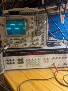
You sure you replaced the right ones George?Distorted square wave, 400 mVpp, 1 kHz input.
Double checked the test equipment by swapping in the digital scope, generator, and cables.
Double checked all preamp settings.
Results are factual.
Now going to sweep it with the QA403.
I'm thinking I'll see a low frequency bump.
I'll also post a 20 kHz photo.
Joe, pretty sure. But I'll open her up and check.
The FR sweep doesn't look good.
I'll be back after I check.
Thanks.

that doesn't matter George, PL just increased the gain in the S2 compared to the S1. About 2:1Yup, I just measured it on the board. The S2 R71 is 7.5k.
Going to take the dog for a walk.
Joe, no problem having this tore down on the bench, this is a test unit I'm using to learn with.
No problem.
Take some time to think about the issue.
I carefully removed the old caps and can easily reinstall them. Nothing to it.
In the meantime I'll carefully measure all the components in that circuit to ensure they're correct.
Something else I wanted to do was measure DC before those 4.7 uF output caps and see what frequency response is with them bypassed.
After sleeping on it, perhaps I'm driving the opamps to distortion levels due to using stepped attenuators for volume and balance controls.
I'll look at that later today.
I constructed the balance attenuator with no resistance at all in the centered position.
Perhaps I need to add resistance at the balance attenuators input tap.
I'll really look at the unit closely with the scope and figure this out.
I'll look at that later today.
I constructed the balance attenuator with no resistance at all in the centered position.
Perhaps I need to add resistance at the balance attenuators input tap.
I'll really look at the unit closely with the scope and figure this out.
You can DC couple them for testing to find out where your mod went wrong. Tack a jumper first across C21 (the 2.2uF cap), check results.Well, nothing wrong with the preamp that I can find.
Doing some reading about square waves, opamps, and rc circuits.
Did it fix it?
No difference with jumper across the 0.22 uF at C21 and C22.
Now going to jumper across the 100 uF at C42 and C43.
In the past, I've found the C42+43 values to be quite sensitive. Tried some 10 uF films there in place of the original 10 uF electrolytics. Sine waves looked good, but audio was degraded somewhat.
This was before I read about square wave testing. Shame, because the fit so well.
Attachments

Hi GeorgeNo difference with jumper across the 0.22 uF at C21 and C22.
Now going to jumper across the 100 uF at C42 and C43.
In the past, I've found the C42+43 values to be quite sensitive. Tried some 10 uF films there in place of the original 10 uF electrolytics. Sine waves looked good, but audio was degraded somewhat.
This was before I read about square wave testing. Shame, because the fit so well.
Good, you narrowed it down...those 2 values really should not be sensitive, Their only function is to dump gain at DC to minimize offset.
Joe, I'm soooo embarrassed.
Rule #1 for square wave testing is DC coupling at the scope.
I've had it set for 50 ohm coupling.
Yes, I broke your rule #1.
And I looked at it several times and didn't see it.
Damn. Starting over, pulling the jumpers and retesting the new caps.
Rule #1 for square wave testing is DC coupling at the scope.
I've had it set for 50 ohm coupling.
Yes, I broke your rule #1.
And I looked at it several times and didn't see it.
Damn. Starting over, pulling the jumpers and retesting the new caps.
I wasn't going to challenge you on the buttons you pushed on your scope George...Joe, I'm soooo embarrassed.
Rule #1 for square wave testing is DC coupling at the scope.
I've had it set for 50 ohm coupling.
Yes, I broke your rule #1.
And I looked at it several times and didn't see it.
Damn. Starting over, pulling the jumpers and retesting the new caps.
")
Don't worry, when things just don't make sense, check your setup.
Well thanks, but I need challenged as I don't have the background for this, I'm more of a mechanic.
Have very nice square waves at 1 kHz.
Here's 20 kHz. Looks good compared to what I've seen on other sites.
Going to be a couple hours or so until I can generate a FR, need to do a few things for the wife, then I can get back to it.
Thanks Joe!
Have very nice square waves at 1 kHz.
Here's 20 kHz. Looks good compared to what I've seen on other sites.
Going to be a couple hours or so until I can generate a FR, need to do a few things for the wife, then I can get back to it.
Thanks Joe!
