
PL2000 preamp square wave ringing.
- Thread starter George S.
- Start date
Joe suggested removing C18 and C20, 33pF caps and replacing them with 15pF caps. Didn't have them on hand, so ordered them. Used silver mica of course.
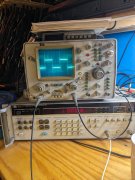
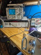
And here's the results at 20 kHz. Tested from 400 Hz all the way to 20 kHz. No ringing!
Once again, thank you Joe.
I'm currently doing some probing to see what components are causing the under and overshoots.
I'm thinking it's cap values.
And here's the results at 20 kHz. Tested from 400 Hz all the way to 20 kHz. No ringing!
Once again, thank you Joe.
I'm currently doing some probing to see what components are causing the under and overshoots.
I'm thinking it's cap values.
Attachments
-
 3.1 MB Views: 14
Joe suggested removing C18 and C20, 33pF caps and replacing them with 15pF caps. Didn't have them on hand, so ordered them. Used silver mica of course.
And here's the results at 20 kHz. Tested from 400 Hz all the way to 20 kHz. No ringing!
Once again, thank you Joe.
I'm currently doing some probing to see what components are causing the under and overshoots.
I'm thinking it's cap values.
And here's the results at 20 kHz. Tested from 400 Hz all the way to 20 kHz. No ringing!
Once again, thank you Joe.
I'm currently doing some probing to see what components are causing the under and overshoots.
I'm thinking it's cap values.
Yeah Kyle, I did some reading and looked at all the photos I could find. Lots of very nasty looking square waves out there.
Really happy with the current results, just going to try to make it better.
Got to get ready to go to town for a classical piano recital the wife got tickets to. Should be fun.
Later y'all.
Really happy with the current results, just going to try to make it better.
Got to get ready to go to town for a classical piano recital the wife got tickets to. Should be fun.
Later y'all.
Joe suggested removing C18 and C20, 33pF caps and replacing them with 15pF caps. Didn't have them on hand, so ordered them. Used silver mica of course.
And here's the results at 20 kHz. Tested from 400 Hz all the way to 20 kHz. No ringing!
Once again, thank you Joe.
I'm currently doing some probing to see what components are causing the under and overshoots.
I'm thinking it's cap values.
And here's the results at 20 kHz. Tested from 400 Hz all the way to 20 kHz. No ringing!
Once again, thank you Joe.
I'm currently doing some probing to see what components are causing the under and overshoots.
I'm thinking it's cap values.
Yup, probes are carefully calibrated.
Using DC coupling for testing, read it's the proper setting for square wave(right or wrong) testing.
Can switch the scopes input to 50 ohms and use a 50 ohm BNC to RCA cable instead of the probe. I get the same results on the CRT.
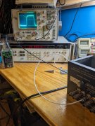
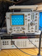
Here's a earlier measurement of a 1 kHz square wave with the 15 pF caps installed.
Interesting thing about the "Ambience" circuit on these is it's always on. Had to refresh my understanding of it by rereading the manual.
It caused a lot of issues with ringing before the cap change, and may still be a issue, we'll see.
The under and overshoots appear to be tone related as I get a better square wave at 10 kHz with the tone controls "flat" and out of circuit.
Going to simply bypass and take portions like the switch PCB out of circuit until I understand what's the offender.
Really didn't have time today to investigate.
Using DC coupling for testing, read it's the proper setting for square wave(right or wrong) testing.
Can switch the scopes input to 50 ohms and use a 50 ohm BNC to RCA cable instead of the probe. I get the same results on the CRT.
Here's a earlier measurement of a 1 kHz square wave with the 15 pF caps installed.
Interesting thing about the "Ambience" circuit on these is it's always on. Had to refresh my understanding of it by rereading the manual.
It caused a lot of issues with ringing before the cap change, and may still be a issue, we'll see.
The under and overshoots appear to be tone related as I get a better square wave at 10 kHz with the tone controls "flat" and out of circuit.
Going to simply bypass and take portions like the switch PCB out of circuit until I understand what's the offender.
Really didn't have time today to investigate.
Attachments
-
 3.5 MB Views: 7
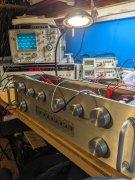
Removed the 15 pF caps and installed 10 pF.
Saw improvement.
Removed the 10 pF and installed very old 7 pF +-5% from my cap collection that tested good.
Saw a slight improvement.
I do have 5 and 2 pF silver mica if I should take it further.
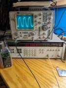
Now getting a nice square wave response at 20 kHz input with the 7 pF silver mica caps installed.
And, the tone control switch in the "flat" position.
Not so good with tone controls engaged. And I think that's because the "Tone Turnovers" are automatically engaged.
So, this shouldn't be a issue, I'm thinking.
Going to button her up and sweep her with the QA403 and see where we're at.
Saw improvement.
Removed the 10 pF and installed very old 7 pF +-5% from my cap collection that tested good.
Saw a slight improvement.
I do have 5 and 2 pF silver mica if I should take it further.
Now getting a nice square wave response at 20 kHz input with the 7 pF silver mica caps installed.
And, the tone control switch in the "flat" position.
Not so good with tone controls engaged. And I think that's because the "Tone Turnovers" are automatically engaged.
So, this shouldn't be a issue, I'm thinking.
Going to button her up and sweep her with the QA403 and see where we're at.
Attachments
-
 3 MB Views: 11
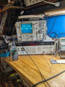
She sweeps flat out to 40 kHz, extremely low noise and distortion.
Been listening to digital Fleetwood Mac with it.
The exercise was well worth doing.
The upper frequencies are clearer and more concise, if that makes sense.
Ordered some more 7 pF caps to do the main systems preamp as I only had two.
Mark L., if you do yours, let us know what you think.
Thanks Joe, couldn't have done it without your help.
Square wave testing, who'da thunk it!
I'd like to do a head to toe write up on what I've learned.
Problem is I'm just a hobbyist lacking the foundation to really understand what Joe and the group has helped me with.
There were power supply issues I couldn't solve to my satisfaction with a onboard transformer, so I recently went offboard with a Power-One Linear Supply.
Also, only in the last week did I get the stepped balance attenuator installed. And, that made a absolutely huge improvement in imaging between the channels.
And yet, I'm not satisfied with the 0.25 dB steps, after testing I want 0.5 dB steps. So I need to build two more, one for the system and another for the test unit. Very labor intensive.
So, it's a work in progress.
Once it's taken as far as possible I'll try to do a writeup.
Any questions, ask and we'll try to answer.
One thing I recently discovered is the issue with the Ambience always in circuit regardless of the switch setting. A stepped attenuator to replace that Ambience pot will fix the issue.
So that's another two attenuators to build and test.
Mark L., if you do yours, let us know what you think.
I used Sine wave testing at 20Hz, 200Hz, 2KHz, 20KHz, and 200KHz because I had a sight notch on the peaks before, now it is gone. The wave forms look perfect, I use the Test Signal Input on Channel 1 as a reference to compare with the preamplifier Output Signal on all Sources except Phono.
This testing brought up a question for those of us testing preamplifiers. What input voltage do you use? I played with 100mV and 500mV. I did not want to go much higher that that.
Interesting thing about the "Ambience" circuit on these is it's always on. Had to refresh my understanding of it by rereading the manual.
Did you try shorting plugs on the Rear Output RCA Jacks?
I swapped in 15pF Silver Mica caps in C18, C20 where I had installed 33pF Silver Mica caps last year. I would like to say I heard a noticeable improvement, but I did not hear any real difference. Although the Channel 2 oscilloscope picture of the PL2000 Output Signal did improve.
I used Sine wave testing at 20Hz, 200Hz, 2KHz, 20KHz, and 200KHz because I had a sight notch on the peaks before, now it is gone. The wave forms look perfect, I use the Test Signal Input on Channel 1 as a reference to compare with the preamplifier Output Signal on all Sources except Phono.
This testing brought up a question for those of us testing preamplifiers. What input voltage do you use? I played with 100mV and 500mV. I did not want to go much higher that that.
On the Ambience pot, I had the wiper wired correctly, but had the resistance strip wired backwards. It does make a difference!
Good idea about scoping the input waveform for comparison to the output waveform. Doing it from now on.
Now have the 15 pF caps back in and resuming the exercise.
Tried the 10 pF, then the 7 pF, again.
Best results again with the 7 pF. Sticking with them.
Mark L., yes, I now see that the Ambience pot turned full ccw does short out the rear channels. Perfect.
Not sure why Marks unit requires a different value cap as the schematics appear the same around that area.
I've got more 7 pF caps coming soon. I'll follow this same procedure with the next unit and see if results are the same or different.
Thanks to all who helped.
Attachments
-
 2.3 MB Views: 6