Universal George, 400s and 700s same.
Not urgent, just passing along a further improvement that can be made.
Not urgent, just passing along a further improvement that can be made.

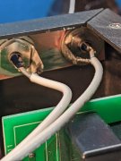
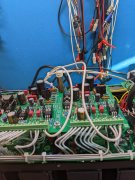
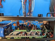
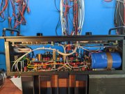
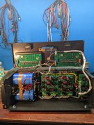
You should now have an even lower noise floor George.Wiring completed. #5 R+L jumper removed. Ground wires run from the copper bus bar to Control Board #5 R+L.
Used 16 AWG grey as I have lots of it, follows the existing wire color selections .
Listening to BTO.
Thanks Joe!You should now have an even lower noise floor George.
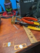
Do you heat it up and wipe it off with a rag?I can clean up those copper plates with my WES 51, takes about 40 seconds..
Anyone have the par number of the 700II meter attenuation switch, been searching and all I find is the power switch. (That is unless I am blind which is a distinct possibility.)I always thought the meters should be accurate like a speedometer on a car.
I do like the meter attenuation switch on the 700 that supposedly matches the 700s meters to a 400s full scale meters. But, you know, I might be wrong about this. I don't know.
Any how, I'll probably put the original resistors back into the 400 S1 so they accurately read 100 watts at the 0 db 100 marking on the meter faces. That's how they designed it, much smarter people than me.
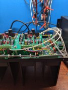
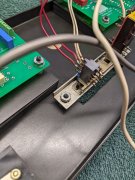
Looks like the power and meter range switch came as a assembly "2-Station ass'y (power & range) ...129-0093-0" mounted on the bracket.
Both switches are Alps, and secured to the mounting bracket with bracket extensions that are crimped to secure the switches.
The meter range switch is very similar to the Alps push button switches in the PL2000 preamps.
These can be taken apart and cleaned, just watch for the spring loaded small parts. I don't remember seeing a part # on my meter range switch, nor see one in the many photos I have of it during the build.
I will keep searching, but that Hafler will work just overkill. Went through Alps catalog and no more bracket slide mount crimp types.Yes sir, that was the original wiring. I've learned to photo pretty much everything electrical before I take it apart. Sure beats drawing it all out like before cell phones!
Found a potential power switch and a meter switch(although it's a little long with extra contacts).
Links follow:
https://www.ebay.com/itm/NOS-HAFLER...2349624.m46890.l49286&mkrid=711-127632-2357-0
https://www.ebay.com/itm/Alps-SDU3P...2349624.m46890.l49286&mkrid=711-127632-2357-0
Many others are listed.