One of my favorites Fred, along with Sublime's Smoke 2 Joints and Wrong Way...Sorry. Any chance to post that tune.
You are using an out of date browser. It may not display this or other websites correctly.
You should upgrade or use an alternative browser.
You should upgrade or use an alternative browser.
PL 700 Pro Build
- Thread starter George S.
- Start date
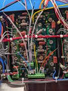
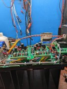
That's how I do it George. It just makes sense.The AC supply to the transformer is rerouted up around the top of the transformer.
I'm taking a different approach with the B- and B+ wires from the rectifier that I almost did on the 400s, but didn't because I hadn't seen it done before. I'm running them directly away from the rectifier and up over the caps, keeping them away from any other wiring. I like this approach better than threading them through under the buss bar.
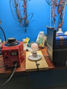
Now following Joe's "Back Plane Bring Up Recommendations" PDF. For those who are new to this, we plug a Variac into the wall, then a Dim Bulb Tester between the Variac and amp.
I like to make the simplest DBT using a 3 wire extension cord. I strip about 4" of insulation off, cut the black wire only, and wire in a 100 watt incandescent light bulb to the two ends.
Any shorts that draw current will light the bulb as voltage is increased on the Variac. The light bulb will take that current saving the amp from errors.
The DCP relays engaged at 80 VAC, that's good.
It's sat here for 10 minutes with power on it. The filiments in the bulb are just barely glowing.
Going to shut it down, discharge the caps, and do the next steps that involve putting in the first row of outputs
Attachments
- Joined
- Jan 14, 2011
- Messages
- 75,914
- Location
- Gillette, Wyo.
- Tagline
- Halfbiass...Electron Herder and Backass Woof
Love the DCP relay clicks!~! Looking good George!
You sure have that right!!!! That click and dim bulb makes my day!Love the DCP relay clicks!~! Looking good George!
- Joined
- Jan 14, 2011
- Messages
- 75,914
- Location
- Gillette, Wyo.
- Tagline
- Halfbiass...Electron Herder and Backass Woof
I think that's a universal feeling around here!!
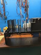
First row of outputs is in with same orange filaments on the DBT and zero volts on the speaker jacks. Next step is to install the control board, repeat using the Variac and DBT. Then adjust Bias.
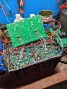
All of the control board wiring has been cut to length and the ends tinned. I use Phoenix Connecters on the back planes and control boards. These are optional, but they make assembly and disassembly a breeze.
All of the control board wiring has been cut to length and the ends tinned. I use Phoenix Connecters on the back planes and control boards. These are optional, but they make assembly and disassembly a breeze.
Attachments
The AC supply to the transformer is rerouted up around the top of the transformer.
I'm taking a different approach with the B- and B+ wires from the rectifier that I almost did on the 400s, but didn't because I hadn't seen it done before. I'm running them directly away from the rectifier and up over the caps, keeping them away from any other wiring. I like this approach better than threading them through under the buss bar.
Beautiful work!
- Joined
- Jan 14, 2011
- Messages
- 75,914
- Location
- Gillette, Wyo.
- Tagline
- Halfbiass...Electron Herder and Backass Woof
Nice George, very nice...
The 3 bias wires on each back plane get dressed for their full length with 1 mm PVC coated woven fiberglass. The rest of the control board wires only need short pieces at their base. Those Phoenix Connecters put the wiring close to a film cap and the bias transistor
Time to take a break and walk the dog. Later.
The fiberglass sheathing is on the Bay from a US seller in NJ, got 1, 8, and 10 mm from them. Many more sizes available from China.
Time to take a break and walk the dog. Later.
The fiberglass sheathing is on the Bay from a US seller in NJ, got 1, 8, and 10 mm from them. Many more sizes available from China.
Attachments
I screwed up on the orientation of the three screw Phoenix Connecters on the control board. As they are now soldered in, they route the bias wires directly over the AC supply wires. The only way to reverse the orientation is to sacrifice the originals and install new ones. Can't get the Hakko desoldering gun down to those solder pads due to all the components around them. Best to just cut them off with the Dremel, extract the leads, and install new ones. Oh well, no big deal, no rush. Need to order cords anyway.
J!m
Veteran and General Yakker
Nothing like a tidy harness.
Yes George, they are supposed to point downwards toward the other wires entering the board.I screwed up on the orientation of the three screw Phoenix Connecters on the control board. As they are now soldered in, they route the bias wires directly over the AC supply wires. The only way to reverse the orientation is to sacrifice the originals and install new ones. Can't get the Hakko desoldering gun down to those solder pads due to all the components around them. Best to just cut them off with the Dremel, extract the leads, and install new ones. Oh well, no big deal, no rush. Need to order cords anyway.
Got clean removal of those two 3 screw Phoenix Connecters. Cut them off with a Dremel cutting wheel, the leads pulled straight out with heat from the iron, then the Hakko desoldering gun cleared the through hole.
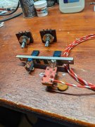
In the meantime I'm starting mock up of the wiring to the power switch and meters on the intermediate plate. New cords and connecters are ordered. Listening to Bachman Turner Overdrive while I work.
In the meantime I'm starting mock up of the wiring to the power switch and meters on the intermediate plate. New cords and connecters are ordered. Listening to Bachman Turner Overdrive while I work.
Attachments
- Joined
- Jan 14, 2011
- Messages
- 75,914
- Location
- Gillette, Wyo.
- Tagline
- Halfbiass...Electron Herder and Backass Woof
A LOT WORSE things you can listen to!!
Got clean removal of those two 3 screw Phoenix Connecters. Cut them off with a Dremel cutting wheel, the leads pulled straight out with heat from the iron, then the Hakko desoldering gun cleared the through hole.
In the meantime I'm starting mock up of the wiring to the power switch and meters on the intermediate plate. New cords and connecters are ordered. Listening to Bachman Turner Overdrive while I work.
Takin care of business...

