PL 700 ii Strange Bias and Offset !! ??

Greg

Journeyman
Joined
Jun 11, 2022
Messages
204
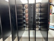
Got a PL 700 ii ebay arrived bent chassis Never tested Bent up

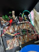
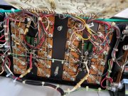
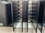
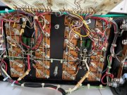
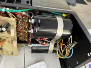
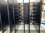
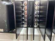
Replaced Chassis remounted with all New matched Output transistors and new Main Power supply CAPS from WO

Did a Vari ac soft start up all went well 90 VDC + & - on both rails this never faulters during intermittent failure always perfect

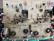
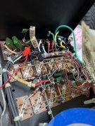
Intermittent issue noted on power up this is what happens on Bad power up

( A ) Bias on both channels starts normal ( .3666 VDC ) then after 2 - 3 seconds goes near Zero VDC ( .0001 VDC )

( B ) At same time Offset ( ON BOTH CHANNELS ) starts at Near ( .0001 VDC ) but after same time 2 -3 seconds goes to ( +28 VDC ) instant then slowly drops about 1 vdc every 3 seconds until it actually flips polarity then continues to rise VDC in reverse polarity about a 1 VDC every 10 seconds.

Alternatively on good start up ( simply resetting power switch ) all is well and stable on both Channels remains stable for a hour

Does this random

IDEAS ?
 

Attachments

  • image0 (1).jpeg
    image0 (1).jpeg
    76.9 KB · Views: 23
  • image1.jpeg
    image1.jpeg
    74 KB · Views: 23
  • image2.jpeg
    image2.jpeg
    57 KB · Views: 21
  • image3.jpeg
    image3.jpeg
    56.5 KB · Views: 19
welcom to the site
was this a full complimentary amp from the factory or has it been converted by you or someone else? What drivers are installed?
More shots of backplate please
with both channels doing this identically you may fist want to check your meter Connections
 
Hello Thanks for interest
The Pl 700 Arrrived as a bit of a Frankenstein
All I have done is replaced all the Main output power transistors as per images
I replaced The main Caps
I replaced The Frame / Chassis

I did NOT Pretest with damaged / Bent Chassis

Its Strange occurrence I have Checked and validated My meter ( FLUKE ) connections against a ( VDC battery ) all seems well

As stated The BIAS ( voltage drop across R 109 (( 10 ohm )) goes Zero at same time the near 28 VDC appears on the Out put channels ( offset ) for both A and B channels ??? in about the 3 second mark

Thanks for any ideas !
 

Attachments

  • today 2.jpeg
    today 2.jpeg
    97.2 KB · Views: 19
  • today 5.jpeg
    today 5.jpeg
    100.5 KB · Views: 19
  • Today1.jpeg
    Today1.jpeg
    98.6 KB · Views: 18
  • today3.jpeg
    today3.jpeg
    61.4 KB · Views: 16
  • today4.jpeg
    today4.jpeg
    105.1 KB · Views: 17
Greg if you posted pictures that are capable of being zoomed in on, it would help this community to help you.
 
50155979-A1C4-4953-8421-41CCDB4F03C9.jpeg
 

Attachments

  • F93C30E1-2CFD-4099-990D-1D7613624ADC.jpeg
    F93C30E1-2CFD-4099-990D-1D7613624ADC.jpeg
    1.6 MB · Views: 12
  • F4222F51-319B-439B-BCE8-E372B0C87919.jpeg
    F4222F51-319B-439B-BCE8-E372B0C87919.jpeg
    2.6 MB · Views: 13
  • 40F4DEDD-55E6-4DE8-AC19-8D7B004296AA.jpeg
    40F4DEDD-55E6-4DE8-AC19-8D7B004296AA.jpeg
    2.7 MB · Views: 22
  • C756EBEE-7DEA-47FA-9C48-36A78358BFF7.jpeg
    C756EBEE-7DEA-47FA-9C48-36A78358BFF7.jpeg
    1.9 MB · Views: 27
  • 07D4D2FF-D25F-4E9B-8A76-C2C5C200E893.jpeg
    07D4D2FF-D25F-4E9B-8A76-C2C5C200E893.jpeg
    1.8 MB · Views: 24
  • 61F4F57A-AB84-4611-A41E-9075F24D38EA.jpeg
    61F4F57A-AB84-4611-A41E-9075F24D38EA.jpeg
    1.1 MB · Views: 17
  • BFA5E85F-BF0C-4F57-9B69-DE4C478B82B7.jpeg
    BFA5E85F-BF0C-4F57-9B69-DE4C478B82B7.jpeg
    1.1 MB · Views: 13
Ok I have reposted images thank you I chose the full image format hope this helps
 
General checks
Double check that OP-amp they should be the same, you have a LM351 , what's that other one?
check Zennor diodes for +15vdc and -15vdc
check voltage between each speaker terminals + and - (LT and RT speaker outupts)
check DC voltage after fuses or backplane.

Might want to run the channel w the LM351 and take the rail fuse out for the other channel
 
What Value are the Sand resistors? should be 7.5k
What was the description for the amp working or not?
The Diodes look funny (might want to check all of them)
 
Yes I noticed op amp are different ordered a pair of LF356N to replace …would these be suitable

also I will Recap the PL36 board to start

Will work on this eve again
 

Attachments

  • 420634CA-ECBC-47C2-8A03-D5DF46AF3A68.png
    420634CA-ECBC-47C2-8A03-D5DF46AF3A68.png
    3.3 MB · Views: 5
What Value are the Sand resistors? should be 7.5k
What was the description for the amp working or not?
The Diodes look funny (might want to check all of them)

Yes well noted the Diodes odd as well. Parts just arrived today will apply repairs and update parts and see how issue progresses
 
Ok I have reposted images thank you I chose the full image format hope this helps
Thanks, much better. Your control board has the famous Rockwood wirewound resistors on it. Those are a known high failure item.

Not your current problem but the Zoebel resistors should never be a wirewound type. Too inductive and defeats the purpose of a Zoebel.
 
Yes but you have to change the R1 and R2 , Looks like you need a 1.8k 5w for the LM356. Might want to add Sockets for the Op-amps.
 

Attachments

  • LM356crop.jpg
    LM356crop.jpg
    200.1 KB · Views: 9
Thanks all for suggestions I will do in the following order rather than shot gun the whole deal if seems and retest after each repair

I am also inclined to install the DC speaker protection relay rather than use my speakers as a test

1. remove ground wire

2. Recap PL36

3. Replace op amps and diodes same time

4. bias transistors replace

Greg
Greg
Sounds Like a Plan.
Very good Idea
I am also inclined to install the DC speaker protection relay rather than use my speakers as a test (still might want to use 2x 8 ohm resistor as your speakers)

Gook luck
Steve
 
Thanks all for suggestions I will do in the following order rather than shot gun the whole deal if seems and retest after each repair

I am also inclined to install the DC speaker protection relay rather than use my speakers as a test

1. remove ground wire

2. Recap PL36

3. Replace op amps and diodes same time

4. bias transistors replace

Greg
Did you check your +/- 15V supplies Greg? Both channels share a common power supply and you indicated both channels are acting up, generally leading to the shared area. Those 7.5K resistors are that power supply.

You should really find out what is up before swapping out parts.
 
Did you check your +/- 15V supplies Greg? Both channels share a common power supply and you indicated both channels are acting up, generally leading to the shared area. Those 7.5K resistors are that power supply.

You should really find out what is up before swapping out parts.
Very good Idea !! Thank you very much I will put that at top of list. Yes it must be part of the shared cct because everything happens at same time both channels !!??
 
Almost like a slow motion latchup that would plague the 14 boards...
 
Very good Idea !! Thank you very much I will put that at top of list. Yes it must be part of the shared cct because everything happens at same time both channels !!??
Dropping 15.5 VDC across each 7.5 K resistor so seems ok
 
Dropping 15.5 VDC across each 7.5 K resistor so seems ok
Greg you should be dropping about 85V across each resistor. The zener voltage is 15V at the downstream end of those resistors.
 
Back
Top