PL 700 II Clair Bros Rising from the Ashes

Peter S

Journeyman
Joined
Jun 29, 2019
Messages
302
Location
Ontario Canada
Things that make you go hummmmmmmmmm...

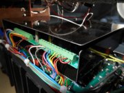
I will do some 'with and without' cover testing and post the results. Even if this works, I believe I will still need to shield the AC wires near the input jacks, as these tests so far have been with no input wiring.

My tests with 1k input presented about 60% less noise than with inputs shunted by 10k. No further noise reduction was noted when 1k was swapped with a dead short (jumper wives). I will do the next tests with 1k on the inputs.

I will post results as soon as I have the wife convinced that I got some work done today, BFN
 

Attachments

Gepetto

Administrator
Staff member
Joined
May 15, 2011
Messages
13,473
Location
Sterling, MA
Tagline
Old 'Arn Enthusiast
Hi Jim;
Sooner or later, I will need to 'drink the water'! I really appreciate the advice and I'm glad that your input is on record in this thread. When doing it 'my way' fails, as it usually does, I will finally have to do it "The right way". I had initially considered shielding the AC wires, but Henry Ott's book says that non-ferrous shielding has no effect on electromagnetic radiation, only electrostatic.
Admittedly, I believe the issue to be capacitive coupling between the AC hot wire and the control board, so copper shielding would help.

I am pursuing my crazy steel box for the control idea because of a (quite possibly hair-brained) theory that when the amp is driven harder and more current flows in Hot and Neutral AC lines, magnetic radiation will be more of an issue. Of course the hum would be harder to hear behind a large signal but still.........I could be all wet here.

Anyway, my steel box is half finished and it will work or I will toss it, and move on to your proven methods.

Thanks All, for your valuable help.....and patience.

PS; Test results to follow asap, but wife telling me to get some work done!
I haven't read his book but I doubt that the book said this...

"but Henry Ott's book says that non-ferrous shielding has no effect on electromagnetic radiation, only electrostatic."

Of course, like anything, it depends on how it is done. Radio waves are electromagnetic waves and shielded wiring, generally speaking, does a very good job of shielding radio waves. A complete, shorted band (like a shield tube) around an electromagnetic source produces a circulating eddy current in that shorted band which produces an (nearly, nothing is perfect) equal and opposite counteracting emag field which effectively kills the emag field effects. Either from getting inside the band or radiating out of the band.
 

BlueCrab

Journeyman
Joined
Nov 10, 2019
Messages
229
Agree, otherwise all that coax cable we use to route low-level audio signals was for naught. Faraday cages do a pretty good job shielding from RF.

Peter, are you now satisfied with the end result, i.e., can you live with the current level of noise reduction? Or is there still a burr under your saddle?
 

grapplesaw

Veteran and General Yakker
Joined
Aug 13, 2014
Messages
2,762
Location
Vancouver
Tagline
---
As to the statement below may I suggest cutting a flat aluminum plate and see what that does in place of the steel one to your measurements, only if you are up to it.

“Henry Ott's book says that non-ferrous shielding has no effect on electromagnetic radiation, only electrostatic.”
 

laatsch55

Administrator,
Staff member
Joined
Jan 14, 2011
Messages
74,124
Location
Gillette, Wyo.
Tagline
Halfbiass...Electron Herder and Backass Woof
I haven't read his book but I doubt that the book said this...

"but Henry Ott's book says that non-ferrous shielding has no effect on electromagnetic radiation, only electrostatic."

Of course, like anything, it depends on how it is done. Radio waves are electromagnetic waves and shielded wiring, generally speaking, does a very good job of shielding radio waves. A complete, shorted band (like a shield tube) around an electromagnetic source produces a circulating eddy current in that shorted band which produces an (nearly, nothing is perfect) equal and opposite counteracting emag field which effectively kills the emag field effects. Either from getting inside the band or radiating out of the band.

So that's how the early eddycurrent VSD's worked eh?
Variation of the eddy current varied the electromagnetic force of the motor??
 

Gepetto

Administrator
Staff member
Joined
May 15, 2011
Messages
13,473
Location
Sterling, MA
Tagline
Old 'Arn Enthusiast
As to the statement below may I suggest cutting a flat aluminum plate and see what that does in place of the steel one to your measurements, only if you are up to it.

“Henry Ott's book says that non-ferrous shielding has no effect on electromagnetic radiation, only electrostatic.”
Hi Glenn
A flat aluminum plate will not have the same type of effect as the loop formed by a cable shield does. Worth a try to see what it may do but it will not work using the same principle that a cable shield does.
 

Peter S

Journeyman
Joined
Jun 29, 2019
Messages
302
Location
Ontario Canada
Pardon me folks---a (very) little knowledge is a dangerous thing. Henry Ott was referring to Magnetic rather than Electromagnetic radiation. That was the thinking when I placed the heavy steel angle over the power transformer (page 19 of this thread).

Admittedly, the hum is likely capacitive coupling between the AC wiring and the sensitive areas on the PL14_20 and (aluminum) shielded AC wiring would probably solve this problem. My reasoning for the steel shield was possible magnetic issues when the amp was driven hard.
 

Attachments

Gepetto

Administrator
Staff member
Joined
May 15, 2011
Messages
13,473
Location
Sterling, MA
Tagline
Old 'Arn Enthusiast
Pardon me folks---a (very) little knowledge is a dangerous thing. Henry Ott was referring to Magnetic rather than Electromagnetic radiation. That was the thinking when I placed the heavy steel angle over the power transformer (page 19 of this thread).

Admittedly, the hum is likely capacitive coupling between the AC wiring and the sensitive areas on the PL14_20 and (aluminum) shielded AC wiring would probably solve this problem. My reasoning for the steel shield was possible magnetic issues when the amp was driven hard.
The angle iron was to see if your problem was stray flux. Stray flux is a magnetic field which is why that was suggested. Now you are determining if your issue is other magnetic (stray flux from the AC wires) or electromagnetic. Carry on with your experiments and keep us informed.

The excerpt from the Henry Ott book you posted is agreed...
 

Peter S

Journeyman
Joined
Jun 29, 2019
Messages
302
Location
Ontario Canada
I suspect that an aluminum shield would have the same positive effect because, I had the hum when power was fed to the terminal strip on the left side, the wiring to the IEC jack was still connected (Joe commented that he could not see the wires as they approached the terminal strip from the under side. If the AC wiring was open-ended, I concluded that there could only be a capacitance coupling to the PL14_20 and aluminum would be an effective shield.

Now that it is working, I want to fix it some more...I need to re-connect input wiring and re-test. I am expecting trouble where the AC wiring approaches the input jacks although this has not been an issue for so many amps. Since the underside of the control board is shield, why not run the AC straight across at the latitude of the of the thermo-switches, avoiding the input corner of the chassis?

I seem to have ignored the whole transformer leaking 62 VAC to the secondary 'thing'. Maybe Perry was right about the transformer being OK?
 

mlucitt

Veteran and General Yakker
Joined
Jun 24, 2011
Messages
3,339
Location
Jacksonville, FL
Could you remind us again where and how the scope is connected. I would be curious to see how the noise is affected now with inputs connected to a preamplifier.
 

Peter S

Journeyman
Joined
Jun 29, 2019
Messages
302
Location
Ontario Canada
Hi Mark;
I have an 8 ohm speaker on each output and the scope is connected on the speaker. The scope is grounded, the amp is not. (and will never be)

I am now wiring inputs. The next test will be with the sig gen grounded, amp floating, scope floating.

BTW; If the noise is 1mV (P to P, I'm guessing that's about 0.350 mV RMS) ) and the output is max 60 V RMS, what is the signal to noise ratio in db?
 
Last edited:

Gepetto

Administrator
Staff member
Joined
May 15, 2011
Messages
13,473
Location
Sterling, MA
Tagline
Old 'Arn Enthusiast
Hi Mark;
I have an 8 ohm speaker on each output and the scope is connected on the speaker. The scope is grounded, the amp is not. (and will never be)

I am now wiring inputs. The next test will be with the sig gen grounded, amp floating, scope floating.

BTW; If the noise is 1mV (P to P, I'm guessing that's about 0.350 mV RMS) ) and the output is max 60 V RMS, what is the signal to noise ratio in db?
69dB
 

grapplesaw

Veteran and General Yakker
Joined
Aug 13, 2014
Messages
2,762
Location
Vancouver
Tagline
---
“I seem to have ignored the whole transformer leaking 62 VAC to the secondary 'thing'. Maybe Perry was right about the transformer being OK?”

Peter I will measure one on the weekend. I remember in the past I measured the low voltage legs to the ground bus and got some wild numbers.
 

Peter S

Journeyman
Joined
Jun 29, 2019
Messages
302
Location
Ontario Canada
Thanks Jim and Joe, I find the 1 mV to be completely inaudible at 6" from the speaker. I hope it stays close to that with input wiring and connection to my signal source.
104.6 db looks respectable, 69 db seems like a Jesus-big clock radio.
Hi Glen, if possible, I would be very interested in the AC voltage on the chassis of your PL amps with reference to the mains neutral (or ground). Measured with the amp powered on but nothing connected (speakers OK). As the secondary centre-tap is tied to the chassis, this would be an indication of primary to secondary leakage.
I believe Henry Ott suggests input wiring as follows for source grounded configurations. Will be back later today with results.
 

Attachments

Peter S

Journeyman
Joined
Jun 29, 2019
Messages
302
Location
Ontario Canada
Well that doesn't work! I can't believe my test speakers survived, they tried to jump off the bench. (loud hum is an understatement). Hum was reduced ( still an awful 60 mv or so) by connecting the shield to pin 2 on the PL14_20.
Trying to connect this amp, with it's chassis buzzing at 60 VAC, to grounded signal source has me stumped at the moment. My last three hairs have falling out....I guess I have to finish Henry Ott's book, or maybe find a different book. My Rane manuals show shields hooked to the input sides.
Very tempted to swap power transformers....
 

grapplesaw

Veteran and General Yakker
Joined
Aug 13, 2014
Messages
2,762
Location
Vancouver
Tagline
---
So I just finished this 700b. I used shielded cable for the ac and got these results.

Right channel - .8mv Ac
Left channel - 1.5mv. Ac

THD+N into 8 ohm loaf resistor

Right channel .04% at 57 volts
Left channel .01% at 57 volts.

The cable shield is grounded one end only to Star ground between power caps.

There is some unshielded ac wire but twisted.
-From outlet plug to fuse and input socket
-One leg running from one high temp switch to the other. It is twisted around the outside of the shielded power cable.

Next one I have sorted how to keep all ac shielded from one end to the other outside the short legs to the high temp switches. 2F18352D-E6CF-4498-8E79-AA124435FFE3.jpeg
 

Attachments

Top