PL 700 II Clair Bros Rising from the Ashes

Peter S

Journeyman
Joined
Jun 29, 2019
Messages
302
Location
Ontario Canada
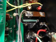
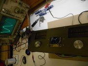
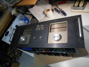
I think this matter is getting under control! I have just re-assembled the amp. As before, a connected speaker is dead quiet with no input connected and Fluke measures 60 VAC to the line ground. The sig gen is not floating, which resulted in the near smoking of the test speaker.
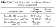
THIS TIME; a jumper clip was put between the wall outlet ground and the PL centre tap bus. Amp is almost perfect! A hum could be detected faintly with ear literally almost touching the speaker... It disappeared completely with the input disconnected.
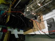
I believe connection to my system should be easier, as star point topology has been observed. The signal generator has a 3 prong plug, so that's asking for trouble!
I would like to run this by the forum: Solution seems to be connect the IEC ground to the cap centre tap bus. This is where the hum is injected (from transformer) so why have it conducted through any other internal wiring?
 

Attachments

Gepetto

Administrator
Staff member
Joined
May 15, 2011
Messages
13,473
Location
Sterling, MA
Tagline
Old 'Arn Enthusiast
Exactly! And if the meter is shunted by 1 Meg, it drops to 43 VAC. Other reliable sources tell me that this (42 uA) is not unsafe. It would have to be 100 times greater to be a safety issue. Nevertheless, it is a huge hum issue
I am not sure if I would call it "exactly" Peter. That is not the way you have it wired up for the testing that you are doing based on your earlier pictures that you shared.

What voltage do you get on your center tap if you disconnect both secondary red wires from the bridge, tape them off and leave them floating? Also curious as to why do you have that voltage on the chassis with nothing connected to it?

What you have is what I sketched below based on your earlier picture that you posted. I can see the large transformer center tap wire going to the disconnected bus bar but it appears that there are 1 or 2 white wires also coming off that bus bar that are heading possibly somewhere? I think you said your 4 caps are 0.22uF so they are quite large connecting the ends of the secondary together as you can see in the sketch.

IMG_1876.jpg
 
Last edited:

Peter S

Journeyman
Joined
Jun 29, 2019
Messages
302
Location
Ontario Canada
You're right Joe, "Exactly" was NOT accurate. Bluecrab's drawing shows the power supply caps still connected. My Electrolytics were disconnected. The AC and Ground to the meters were disconnected at the meters. Wires to the Speaker black terminal bus were left because these terminals were left unconnected. The 'Snubber' caps were disconnected.
I left only the bridge connected to the secondary because I did not want subject these wires to the stress my removal process as they are short as it is.
Even the slightest voltage induced by capacitance (or insulation leakage or whatever is going here) if the chassis is left floating, wouldn't a loop always be formed by the input ground to the source equipment if it has any reference to ground?
 

Peter S

Journeyman
Joined
Jun 29, 2019
Messages
302
Location
Ontario Canada
Yes my snubbers are .33 uf 630 V They were new and handy, so I used them. I was assured that the larger size was OK.. The amp is dead quiet. No hum unless it is buried in the background hash viewed on the scope at max sensitivity.
Put the amp on the 8 Ohm dummy load; 60.7 VAC at 1 kHz, Left of Right, just before clipping. Both channels still measure 0 mV DC offset.
..............Wow.........Can't wait to put this amp in my rack. Cleaned the meters, face-plate still needs work but I had to get a sneak-peek. The handle were from Home Depot, $3 ea.
 

Attachments

Peter S

Journeyman
Joined
Jun 29, 2019
Messages
302
Location
Ontario Canada
I think my celebrations were a little premature... There is a low level hum when the volume pots are opened. Dead quiet when pots are closed. Obviously the 'leaky' power transformer has got something to do with it but the amp. I am still hoping that this is a solvable problem.
 

FredR

Chief Journeyman
Joined
Jan 26, 2014
Messages
1,469
Location
DFW
Tagline
WTF?
Get low hum on my 700s. Independent of gain. Seems if the gain effects it, maybe it's coming in the inputs.
 

BlueCrab

Journeyman
Joined
Nov 10, 2019
Messages
229
I would not jump to the conclusion the hum is somehow due to the transformer. Maybe, but keep an open mind. There are other possibilities as suggested above. Is it on both channels? Can you see it on a scope (and hence measure it). Try shorting the inputs to shield - and this has to be a real short, not a alligator jumper from input to shield as that length of wire is enough to induce a hum. Best to make a short with an old plug. Is it still there after shorting the inputs?
 

Peter S

Journeyman
Joined
Jun 29, 2019
Messages
302
Location
Ontario Canada
I may have alienated some folks here by connecting the transformer centre tap to the IEC line cord jack (via #14 wire). This can easily be 'undone' but it was my solution to the ac leakage in the secondary. The transformer may still prove to be defective but some have suggested that 46 uA through 1 Meg ohm is acceptable.
In any case, if there is a ground loop, why not just open the loop?
I appreciate all that have stuck with me through this 'odyssey'. I will try to follow through with every question or suggestion regarding this problem.

Hi Fred; I have 2 an original PL700 and a 700B, both are dead quiet (<.001 mV) hum or noise, wide open.
Thanks BlueCrab. I have the amp near my main system, for testing. The line arrays have been disconnected. A sacrificial speaker has been connected to each channel.
Amp plugged in with 3 wire IEC cord (CT tap connected to mains ground) Inputs open (nothing connected) amp is quiet with volume pots at max or min. Minor buzzing hum at 50% pot position. Same results with inputs plugged with a shorted plug.
With amp connected with Mains ground not connected, the amp quieter (<.001 mV) regardless of pot position. But there is 35 VAC on the chassis and input ground. I am going to have to build up some nerve to connect it even the signal generator. I am concerned about damaging the DSP (system signal source)
 

FredR

Chief Journeyman
Joined
Jan 26, 2014
Messages
1,469
Location
DFW
Tagline
WTF?
One day I'll get around to troubleshooting. :) Noise floor is still very low. No alienation here. Your amp, you can do what you want. Hell knows I do.
 

BlueCrab

Journeyman
Joined
Nov 10, 2019
Messages
229
Peter, in my opinion, the chassis and signal ground should be kept separate. That is, signal ground is not connected to the chassis. The sketch below shows the idea. The signal ground which is connected to the center tap of the secondary is not connected to the chassis. The AC power earth from the power cord can then be connected to the chassis and should provide some shielding protection to the circuits of the amplifier. I have seen some equipment where the signal ground is connected to the chassis through a capacitor in the range of 0.01 to 0.1uF.
PL Ground.jpeg
 

Peter S

Journeyman
Joined
Jun 29, 2019
Messages
302
Location
Ontario Canada
Hi BlueCrab, thanks for the drawing.
I have a leakage (probably capacitive coupling) between the primary and secondary windings. I measure 60 VAC to the transformer sec. centre tap. As mentioned, it drops to 40 VAC through 1 Meg, and so on (see above). I am afraid that the transformer has some issues. It appears that 42 uA is not a safety issue but I am trying to find a grounding configuration that will work, given this leakage. I have a second PL700 series II, to be "WOPL'ed" and the transformer seems to have the same leakage....seems unlikely.
If my amp was wired according to your sketch, there would be 60 VAC from audio ground to chassis ground.
 

BlueCrab

Journeyman
Joined
Nov 10, 2019
Messages
229
Sorry Peter, you're missing the point. All transformers will exhibit this behavior - it's inherent and is expected, there is nothing wrong with your transformer. If you isolate the signal ground plane (i.e. the secondary center tap from the chassis) from the earth ground of the plug, the "leakage" will go away. This means the signal ground will no longer be connected to the chassis AND the earth ground of the plug should go to the chassis ONLY (don't connect it to the center tap of the secondary).

It seems most (if not all) are not connecting the amp with a 2-prong AC plug and not connecting an earth ground.
 

grapplesaw

Veteran and General Yakker
Joined
Aug 13, 2014
Messages
2,762
Location
Vancouver
Tagline
---
Why are guys still trying to ground main supply to the chassis?? It’s not built that way. These transformers are not total isolation transformers.

You have to test the supply after the bridge rectifier. There are all sorts of stray voltage measurements in what you are testing. Measure main power caps to center for Ac voltage. Each Rail should be 104 to 108 dc. Ac should be minimal.

Sounds like you have a good amp with possible ground fault after bridged power supply. Look for that first. It is there and you missed it.
 

mlucitt

Veteran and General Yakker
Joined
Jun 24, 2011
Messages
3,339
Location
Jacksonville, FL
Except for the Earth wire connected to the chassis and the Thermal Cutout on the Neutral leg, this schematic is very similar to the drawing above. Because you have half of your AC supply connected to the chassis, have you tried isolating the metal case of bridge rectifier from the chassis?

PL700B Power Supply.png
 

Peter S

Journeyman
Joined
Jun 29, 2019
Messages
302
Location
Ontario Canada
I have measured other transformers and found voltage from Primary to secondary, but this transformer had the most voltage. I am prepared to open this amp again and try any suggestions. To review the centre tap measured 60 VAC to the neutral side of the primary, dropping to 42 VAC through 1 Meg ohm with the transformer physically removed from the chassis, EVERTHING disconnected from the secondary including snubbers and filter caps. I only left the bridge (with no snubbers) connected. Bridge was lifted from saddle. All connections to centre tap buss bar disconnected. 12 AC winding disconnected from meters.
 

grapplesaw

Veteran and General Yakker
Joined
Aug 13, 2014
Messages
2,762
Location
Vancouver
Tagline
---
Please measure across main power caps. What do you have when you do that for readings? You can also measure same point with with four rail fuses out and compare. You should have 104-108 DC volts across these caps. If you do then the transformer is working correctly
 
Last edited:

Peter S

Journeyman
Joined
Jun 29, 2019
Messages
302
Location
Ontario Canada
Hi Grapple, the caps measure about 101 VDC + & -, relative to the centre tap. But the centre tap measures 60 VAC to the neutral side of the primary.
 
Top