WOPL Sniffer
Veteran and General Yakker
If i'm troubleshoting an amp problem, Star ground is my reference.

Perry;
The secondary centre tap is 60 VAC above earth ground. The wall outlet ground is my simplest connection to earth ground and only a temporary measurement. I very much appreciate all advice but please follow the thread closely. The chassis has an undeniable spurious voltage on it.
What would you use as a reference point?
New bias transistors installed. The old PL700 measures about 600 mV AC to earth ground power on, about 1.3 VAC with the amp switched off.
With input RCA's connected, zero volts (speaker negative to earth ground)
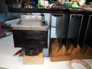
Perry......again; Yes it is probably something I have done incorrectly, but the transformer has been completely isolated from the amp. The back planes could WELDED to the chassis and not have an influence on this issue. Could you indicate which entry in this thread shows cold solder joints?