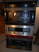
PL 700 II Clair Bros Rising from the Ashes

MarkWComer

Veteran and General Yakker
Joined
Nov 1, 2014
Messages
3,246
Location
Gaston, SC
Tagline
Victim of the record bug since age five
I think there were a few builds where they sanded the edges down a bit, but I also dimly remember Joe changing the board size a nip for more clearance.
 

Gepetto

Administrator
Staff member
Joined
May 15, 2011
Messages
13,553
Location
Sterling, MA
Tagline
Old 'Arn Enthusiast
I think there were a few builds where they sanded the edges down a bit, but I also dimly remember Joe changing the board size a nip for more clearance.
True that, we accommodated the sloppy dimension control that PL had on the Series 2 with the RevA backplanes (which were taller). Squeezed it down with RevB to ensure they fit.
 
Last edited:

FredR

Chief Journeyman
Joined
Jan 26, 2014
Messages
1,477
Location
DFW
Tagline
WTF?
True that, we accommodated the sloppy dimension control that PL had on the Series 2 with the RevB backplanes. Squeezed it down to ensure they fit.
Much prefer the new White Oak chassis. Always will use them except when the steel Clair Bros chassis is under the knife.
 

WOPL Sniffer

Veteran and General Yakker
Joined
Aug 10, 2015
Messages
11,230
Location
Minnie-Soda
Tagline
Screw it
The Clair bros chassis will work with the WO Back Planes, but it can be tight. Just leave all the mounting posts for the Bias tranny, and middle posts loose, and ensure you have clearance when looking for the mounting holes for the outputs(and the emitter base pins.... . I DID DOZENS.... I found the best way is to drill the mounting post holes out a bit (the bias tranny mount hole at the bottom and the one in the middle. Leave everything loose till you get a top row, and bottom row of outputs in..... I put them all in at once since I have done so many and never had a Dumb Bulb Problem for years. But you can put some screw and white spacers up top where the last row goes to keep it all lined up. It's fun. I think some of the guys have sanded the edges of the boards but I don't
 

Peter S

Journeyman
Joined
Jun 29, 2019
Messages
307
Location
Ontario Canada
Thanks guys;
I'm always looking for imaginary problems if I don't have real ones handy! On that note; I was happy to see that the Clair Bros amps have 1/4" phone jacks rather than RCA's. I saw fiber washers under the nuts, so I figured that's something to do with the 'star topology' ground scheme. I was really hoping to leave the input wiring alone. A faint voice suggested "Strip amp existing wiring and innards." so, oddly enough, I decided to follow instructions. It seems the fiber washer is just for show, the 1/4" phone jack is in direct contact with the chassis on the inside........Is this OK? That would make two ground connections to the chassis.
 

Attachments

Peter S

Journeyman
Joined
Jun 29, 2019
Messages
307
Location
Ontario Canada
It's getting more and more mysterious; the "Direct / Normal" switch is also just there for show! I just checked my second Clair Bros amp and it is the same. The centre switch contact has been removed. Is there any point in replacing the switch and restoring the coupling cap bypass function. The amp will be driven by a "miniDSP" that no-doubt has coupling caps in the output ( haven't checked though). Would bypassing this cap improve frequency response or phase shift?---even in the slightest?
A simple jumper from the stub remaining from the centre contact to the remaining appropriate side of the switch, would restore function. Is this a good idea?
Thanks again everyone, Peter in Canada
 

Attachments

Gepetto

Administrator
Staff member
Joined
May 15, 2011
Messages
13,553
Location
Sterling, MA
Tagline
Old 'Arn Enthusiast
Thanks guys;
I'm always looking for imaginary problems if I don't have real ones handy! On that note; I was happy to see that the Clair Bros amps have 1/4" phone jacks rather than RCA's. I saw fiber washers under the nuts, so I figured that's something to do with the 'star topology' ground scheme. I was really hoping to leave the input wiring alone. A faint voice suggested "Strip amp existing wiring and innards." so, oddly enough, I decided to follow instructions. It seems the fiber washer is just for show, the 1/4" phone jack is in direct contact with the chassis on the inside........Is this OK? That would make two ground connections to the chassis.
Not OK unless you want ground loop Peter. Unfortunately, phone jacks are pretty poor connections but the pro audio community likes them because they are big and robust.
 

mlucitt

Veteran and General Yakker
Joined
Jun 24, 2011
Messages
3,375
Location
Jacksonville, FL
"It's getting more and more mysterious; the "Direct / Normal" switch is also just there for show!" - Peter

And the ground wires leading to the tab under that switch are likely making less than ideal contact.
 

MarkWComer

Veteran and General Yakker
Joined
Nov 1, 2014
Messages
3,246
Location
Gaston, SC
Tagline
Victim of the record bug since age five
It's getting more and more mysterious; the "Direct / Normal" switch is also just there for show! I just checked my second Clair Bros amp and it is the same. The centre switch contact has been removed. Is there any point in replacing the switch and restoring the coupling cap bypass function. The amp will be driven by a "miniDSP" that no-doubt has coupling caps in the output ( haven't checked though). Would bypassing this cap improve frequency response or phase shift?---even in the slightest?
A simple jumper from the stub remaining from the centre contact to the remaining appropriate side of the switch, would restore function. Is this a good idea?
Thanks again everyone, Peter in Canada
NO! Examine that wiring closely- it kicked my butt at first, too...

Only a double-pole single throw switch is needed here. Look at the wiring- when the switch is open, the input from the jack must go through the cap, then to the other pole of the switch- the input cable. With the switch closed, the cap is shunted, the input jack is now directly connected to the input cable.
 

MarkWComer

Veteran and General Yakker
Joined
Nov 1, 2014
Messages
3,246
Location
Gaston, SC
Tagline
Victim of the record bug since age five
Thanks guys;
I'm always looking for imaginary problems if I don't have real ones handy! On that note; I was happy to see that the Clair Bros amps have 1/4" phone jacks rather than RCA's. I saw fiber washers under the nuts, so I figured that's something to do with the 'star topology' ground scheme. I was really hoping to leave the input wiring alone. A faint voice suggested "Strip amp existing wiring and innards." so, oddly enough, I decided to follow instructions. It seems the fiber washer is just for show, the 1/4" phone jack is in direct contact with the chassis on the inside........Is this OK? That would make two ground connections to the chassis.
Isolate signal ground from chassis (ground). I can’t speak for why yours are in direct contact with the chassis other than the 1/4” jacks being too big for the hole. On my 700 there was a ground bus on the input jacks, the metal body of the Direct/normal switch was connected to it. So again, this ground had to be eliminated.
 

Peter S

Journeyman
Joined
Jun 29, 2019
Messages
307
Location
Ontario Canada
Hi Mark and All;
I checked the switch again, and the cap is not bypassed in either switch position (I verified this with my Fluke meter). My camera is not the best and the switch is very corroded, making it difficult to see that the switch is being used only as binding posts for the caps. The centre contacts of the DPDT switch have been broken off.
Is this a Clair Bros mod; to have the Direct Coupling defeated? Mark, I've triple checked this now!--honest!
Regarding the input jacks; so it's a thumbs down on the 1/4" phones......In their defense, I've had grief with the RCA's on my original PL700 (off-set meters). How about using 1/4" Stereo (TRS) jacks and using the ring as ground for the PL and tying the cable shield to the sleeve?
 

62vauxhall

Veteran and General Yakker
Joined
May 14, 2014
Messages
2,289
Location
Southwest Kootenays BC
Tagline
No such things as bad days, just bad moments
FWIW, I lived with 1/4” jacks on a 700B for years. When I first dove into it, prior to a White Oak conversion, one of the first things I did was change them out for RCA’s. Since every pre-amp I was connecting to it and all patch cords I had were RCA, it made more sense to me. Plus I no longer had to dick around with adaptors. I never cared for how far that assembly protruded out the back.
 

MarkWComer

Veteran and General Yakker
Joined
Nov 1, 2014
Messages
3,246
Location
Gaston, SC
Tagline
Victim of the record bug since age five
Hi Mark and All;
I checked the switch again, and the cap is not bypassed in either switch position (I verified this with my Fluke meter). My camera is not the best and the switch is very corroded, making it difficult to see that the switch is being used only as binding posts for the caps. The centre contacts of the DPDT switch have been broken off.
Is this a Clair Bros mod; to have the Direct Coupling defeated? Mark, I've triple checked this now!--honest!
Regarding the input jacks; so it's a thumbs down on the 1/4" phones......In their defense, I've had grief with the RCA's on my original PL700 (off-set meters). How about using 1/4" Stereo (TRS) jacks and using the ring as ground for the PL and tying the cable shield to the sleeve?
Yeh, looks funky enough. Ol’ rusty thing should be replaced anyway...

Well, if that indeed is a DPDT, it is surely “locked in” to normal coupling. I’ve seen switches like that where the center contacts aren’t contacts- they’re crimp tabs to hold the thing together. They look too close together to be an actual contact, not inline with the positions of the switch.

If anything, Clair would have gone for direct-connect only, as this was for use in sound reinforcement applications. The “normal” position was for use in home audio applications. As for the 1/4” phone jacks, I’d change them just for the sake of compatibility with the usual and customary RCA connectors. That’s up to you- and I think someone else posted about using XLR connectors- but that was yet another pro application.

Regardless, looks like you’re going to change all this out anyway, and will probably fix the error.
 
Last edited:

FredR

Chief Journeyman
Joined
Jan 26, 2014
Messages
1,477
Location
DFW
Tagline
WTF?
Yeh, looks funky enough. Ol’ rusty thing should be replaced anyway...

Well, if that indeed is a DPDT, it is surely “locked in” to normal coupling. I’ve seen switches like that where the center contacts aren’t contacts- they’re crimp tabs to hold the thing together. They look too close together to be an actual contact, not inline with the positions of the switch.

If anything, Clair would have gone for direct-connect only, as this was for use in sound reinforcement applications. The “normal” position was for use in home audio applications. As for the 1/4” phone jacks, I’d change them just for the sake of compatibility with the usual and customary RCA connectors. That’s up to you- and I think someone else posted about using XLR connectors- but that was yet another pro application.

Regardless, looks like you’re going to change all this out anyway, and will probably fix the error.
The two Clairs I have both have the switch. If it actually bypassed the capacitor Perry would know.
 

Peter S

Journeyman
Joined
Jun 29, 2019
Messages
307
Location
Ontario Canada
Thanks guys;
I'm new here so I'm not sure which entries are Perry's. He must a tremendous authority regarding PL's. Even Joe has referred me to him. How does one contact Perry?
Since we're at the stripped down chassis stage, I've never liked the hard-wired line cords on PL's. I just saw the WO chassis on 'fleabay'---WOW! Joe has thought of everything! An IEC power inlet!...........the gears are turning. What if I mounted the line fuse internally and opened up the line fuse hole for an IEC C-14 plug?------------nope, scratch that idea; strain relief hole is too close to the bottom of the chassis.

How about loosing the fan outlet and turning it into an IEC plug? Is this too much butchery? I have never plugged anything else into this outlet anyway---and why have more AC current than necessary through the internal wiring.

Or.....just buy some new 14-2 power cord and enlarge the existing line cord hole for a slightly larger Heyco strain relief?

OORRR--maybe don't fix it if it ain't broke? Thoughts anyone?
 

FredR

Chief Journeyman
Joined
Jan 26, 2014
Messages
1,477
Location
DFW
Tagline
WTF?
I always put in a new power cord when I WOPL an amp. It will help if you buy a Heyco tool. Joe's chassis makes that unnecessary.
 

Gepetto

Administrator
Staff member
Joined
May 15, 2011
Messages
13,553
Location
Sterling, MA
Tagline
Old 'Arn Enthusiast
Thanks guys;
I'm new here so I'm not sure which entries are Perry's. He must a tremendous authority regarding PL's. Even Joe has referred me to him. How does one contact Perry?
Since we're at the stripped down chassis stage, I've never liked the hard-wired line cords on PL's. I just saw the WO chassis on 'fleabay'---WOW! Joe has thought of everything! An IEC power inlet!...........the gears are turning. What if I mounted the line fuse internally and opened up the line fuse hole for an IEC C-14 plug?------------nope, scratch that idea; strain relief hole is too close to the bottom of the chassis.

How about loosing the fan outlet and turning it into an IEC plug? Is this too much butchery? I have never plugged anything else into this outlet anyway---and why have more AC current than necessary through the internal wiring.

Or.....just buy some new 14-2 power cord and enlarge the existing line cord hole for a slightly larger Heyco strain relief?

OORRR--maybe don't fix it if it ain't broke? Thoughts anyone?
Or put a beautiful chassis into your project and get rid of that painted steel thing... :)
 

Peter S

Journeyman
Joined
Jun 29, 2019
Messages
307
Location
Ontario Canada
Thanks Fred;
I think I have heard of replacement face plates available. If we could find a source for new power transformers, would we even need to start with an old PL to build a WOPL?---just kidding, Joe (sort of)!

I have run separate lines from my power panel with 4 breakers, one for each power amp and the forth for signal level equipment. Unfortunately, the amp would require an almost 8 foot line cord to reach the four-gang outlet. I was aiming to have the outlets behind the amp rack when we designed the house, but the wife did not want the amplifiers to be the focus of the living room---some women are crazy! Would 8 feet of 16 gauge line cord be a line-loss issue?
 

Attachments

Top