Summary of PL 4000 issues found in my father's units ( S/N 3xxx and 4xxx ):
- rear connectors
- difficult cleannig switches
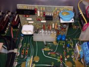
- bad contacts betweeen mother board and front panel board
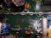
- bad contacts between peak unlimiter board and mother board
( big board with a little connector in the center )
-caps wrong ( only 35V ; necessary 50 / 63 V) ( fixed after S/N 5000 )
- Pcb board tracks of all boards very fragile .
2nd version of mother board and front panel board is O.K.
Ed ,
can you confirm ?
Ciao
Marco
Marco,
Yes there were problems with the rear connectors (RCA jacks) cracking and breaking.
The early 4000's that used Molex connectors between the front panel pc board and motherboard had issues. Most of these units did not have the slide out bottom cover like the later units had which also made them more difficult to work on. These units had a bottom plate which is one piece with the sub-front panel.
My neighbor Dean stopped working on these earlier units many years ago. His comment was that even if he fixed all the problems he could guarantee that the problems would come back later. As a matter of fact when a customer brought an early unit (less than S/N 1500 or so) he would walk them over to my house and have me trade them a newer 4000 that had already been gone through by Dean and I. I would also give them a $100 credit for their old 4000. Eventually I had a pile of these that Dean would no longer work on. Needless to say, just before I moved from the Seattle area to Connecticut (where I am now) I sold them all as-is on ebay.
Later units after S/N 1500 used 90 degree headers soldered directly between the motherboard and front panel pc board which eliminated the problem. NOTE: Neither Dean or I had any spare 90 degree headers to install.
All of the other 4000's have issues as well because of the Molex connectors between the daughter board and motherboards. The solder joints on all the Molex connectors on the motherboard and daughter (plug-in) boards also need to be redone. Additionally all of the potentiometers and switches need to be cleaned/lubricated.
I hate mechanical connections!
Even though, in general I do not recommend replacement of all electrolytic capacitors in audio components, I would say that with the Phase Linear 4000 series 1's and 700 series 1's (with the PL10171 pc board) and 400 series 1's (with the PL400C pc board) that the electrolytics should be replaced. NOTE: Some brand were better/ more reliable than other. As an example the Nichicon's were among the best Phase Linear used. However the 4000's did use some IEC brand that we had issues with (see service bulletin noted below). The 700 and 400 pc boards noted above used brands of electrolytics that Phase Linear stopped using by approximately 1974 and many of the pcb electrolytic capacitor issues we see today don't appear with the models after 1974. The exception being the 100uF caps when an amp has failed. The power supply caps used in their amplifiers has also been an issue with
certain brands as well. As an example, Temple, FAO, and STM come to mind.
The last Phase Linear service bulletin that Dean ever issued is concerning the electrolytic capacitors and is the 6/00 (June 2000) bulletin released on the web site I shared with him.
https://web.archive.org/web/20080705234211/http://www.hometown.aol.com/phasetek/capbull.html This bulletin also describes the power supply capacitors and the 50/63 V caps you mention above.
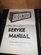
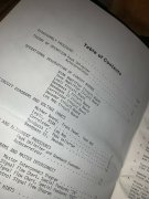
I would recommend for anyone servicing a 4000 series 1 preamplifier that you obtain the 6/81 revision of the service manual.
I haven't had too many problems with pcb traces. Then again I don't use temperatures exceeding 700F or place the tip in contact longer than approx 2 or 3 seconds.
Ed