Phase Linear 4000 Restoration

oldphaser

Chief Journeyman
Joined
Sep 8, 2012
Messages
845
#21
I recently purchased this actual PL 4000 and am trying to restore it. The unit has a PL30 in place of the PL03 Tone Amp board and no Decoder board PL06 as shown in the photo, the white wires running from the PL30 to the socket of the PL06. Does anyone have information on this modification?
What you need is the later 6/81 version of the Phase Linear 4000 series 1 service manual. Not the earlier 6/76 version.
Ed
 

BlueCrab

Journeyman
Joined
Nov 10, 2019
Messages
229
#22
Today I received the Service Documentation sold on EBay. This shows all - the early versions as well as the last. The online (free) documentation is missing a bunch of information and is not recommended. The EBay docs are expensive, but worth it. It has the artwork and schematic of the PL30 card and gives me full documents for everything. If you're going to service one of these beasts, I recommend it.

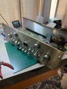
I also received my order from Mouser to begin the re-cap of the unit. Motherboard and front board are complete - controls cleaned or lubed as appropriate and likewise the board connectors. Whoever soldered this unit in the passed used the motto, "the bigger the blob, the better the job" as there were some enormous solder blobs on the motherboard. These have been removed. I also loath remnants of solder flux, so the boards have been cleaned of excess solder flux. With this many connections cleanliness will be crucial. Began putting the chassis back together and have learned the lesson not to forget installing the selector switch and volume control before putting the front panel on. I am now properly trained, but will duly forget this the next time the front panel comes off. Next step will be to re-cap the individual boards. Here's a current photo:
View attachment 37866
 

Attachments

marcok

Chief Journeyman
Joined
Jun 9, 2014
Messages
994
Location
Milan Italy
Tagline
I'm very curious about any tech item
#24
Trust me ,replace all rear connectors ! They are a time bomb !
At present I'm sure they work , but in the future , when plug inserted , they will brak .
Reason : fragile plastic and the pressure of the plugs .
I had to replace them in 2 PL 4000 and in one PL 1000.
Pics are available on my posts .
Ciao
Marco
 

BlueCrab

Journeyman
Joined
Nov 10, 2019
Messages
229
#25
Got it, Marco. Thanks for the warning.

What I would give for an Italian coffee and pastry in one of your bars. Best in the world!
 

marcok

Chief Journeyman
Joined
Jun 9, 2014
Messages
994
Location
Milan Italy
Tagline
I'm very curious about any tech item
#26
https://www.audioskeggia.com/connet...ri-rca-da-pannello-femmina-6605262555219.html
These are the right connectors ( with two plastic washers ) . Very easy to find .
Prepare 44 wires 4/5 cm . long and solder . Easy but long job .
Another little suggestion : deox the switches through the 2 small holes on the top .
On the front side it's useless . Insert the needle of a syringe into the holes , insert the straw of deox into the needle and spray .
Ciao
Marco
P.S: Thank you for virtual coffee .
 

Wheel-right

Chief Journeyman
Joined
Jun 24, 2019
Messages
781
Location
SoCal
Tagline
Man, Ya shoulda been here yesterday
#27
https://www.audioskeggia.com/connet...ri-rca-da-pannello-femmina-6605262555219.html
These are the right connectors ( with two plastic washers ) . Very easy to find .
Prepare 44 wires 4/5 cm . long and solder . Easy but long job .
Another little suggestion : deox the switches through the 2 small holes on the top .
On the front side it's useless . Insert the needle of a syringe into the holes , insert the straw of deox into the needle and spray .
Ciao
Marco
P.S: Thank you for virtual coffee .
On my 2000 Series II, I used a small syringe with needle attached to clean all the controls, much more control than trying to spray out of those cans. Less mess , better job.
 

BlueCrab

Journeyman
Joined
Nov 10, 2019
Messages
229
#28
So... It's all back together - and working. There are, however, some interesting discoveries. After putting it back together and performing some initial checks, I began running the Test Procedures outlined in the service manual. Everything checked okay except the Active Equalizer at the 20kHz frequency. Instead of getting a 2 to 4dB increase, mine was ruler flat. This is a relatively minor issue, but being an engineer, I wanted to know why and began to dig deeper. The Active Equalizer is supposed to provide, when active, a 7-9dB boost at the low frequencies (20Hz) and a 2-4dB boost at 20kHz. The circuitry that does this resides mostly on the Tone Amplifier along with an RC network of the front panel made up of R58/C28 and R59/C29. When I looked on the front panel for these components, I found nothing. They are missing. I suspect they have been removed, since their mounting holes are soldered over, but it's possible they were never installed.
 

marcok

Chief Journeyman
Joined
Jun 9, 2014
Messages
994
Location
Milan Italy
Tagline
I'm very curious about any tech item
#30
20 kHz ? The purpose is to compensate the low frequency roll off of most speakers .
20 KHz is useless unless you are a "bat ".
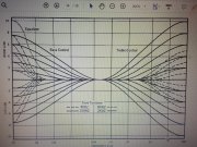
The active equalizer has a 6 dB / oct slope under 50 Hz .
See owner's manual . You'll find all the curves of filters .
At present The Carver Site has problems .
Try with HiFi engine .

Ciao
Marco
 

oldphaser

Chief Journeyman
Joined
Sep 8, 2012
Messages
845
#31
So... It's all back together - and working. There are, however, some interesting discoveries. After putting it back together and performing some initial checks, I began running the Test Procedures outlined in the service manual. Everything checked okay except the Active Equalizer at the 20kHz frequency. Instead of getting a 2 to 4dB increase, mine was ruler flat. This is a relatively minor issue, but being an engineer, I wanted to know why and began to dig deeper. The Active Equalizer is supposed to provide, when active, a 7-9dB boost at the low frequencies (20Hz) and a 2-4dB boost at 20kHz. The circuitry that does this resides mostly on the Tone Amplifier along with an RC network of the front panel made up of R58/C28 and R59/C29. When I looked on the front panel for these components, I found nothing. They are missing. I suspect they have been removed, since their mounting holes are soldered over, but it's possible they were never installed.
I had to grin a little when I saw your post.

It amazes me how many times I see someone selling a 4000 on ebay stating that it works perfectly. When if in fact they tried to use the "test procedures" in the service manual they would run into what you did. Either they would choose to ignore it or attempt to do something about it.

Please allow me to step back in time a little bit. Many years ago I had a stack of 4000's (S/N greater than 2500) I had accumulated. I had gone through them all doing the normal repairs that I do, re-doing all the solder joints on the motherboards and "daughter" boards, replacing electrolytic capacitors, cleaning/lubricating potentiometers, switches, etc. Then came time for testing and I ran into exactly what you did with every single one of my 4000's.

Reading the service manual it states:
7. Switch the ACTIVE EQUALIZER in(up) and verify less than 2dB change in output signal level at 2KHz
8. Repeat step 7 above at 20Hz and verify an increase of 7 to 10dB in output signal level.
9. On models with serial number greater than 2500 repeat step 7 above at 20KHz and verify an increase of 2 to 4dB in output signal.

I walked 2 houses down to my neighbor Dean Nissen's house. (NOTE: Dean was the last factory service manager at Phase Linear.) I asked Dean about this since he would know the answer and he was the one who last revised the service manual in 6/1981.

Dean informed me that indeed Phase Linear made a change at serial number 2500 but they (Phase Linear) decided later on to change the circuit back to what it was before then. Unfortunately, there is no notation in the service manual at what serial number this change back to what is was before S/N 2500 occurred out.

I also have a marked up copy of Dean's service manual and he makes no notation about this in it.

So whenever I would sell any of the 4000's I had on ebay, I would state that I followed the test procedures as outlined in the service manual along with the knowledge I had gained with working with Dean for over 25 years!


Ed
 
Last edited:

marcok

Chief Journeyman
Joined
Jun 9, 2014
Messages
994
Location
Milan Italy
Tagline
I'm very curious about any tech item
#33
Ed ,
for me active equalizer is not a sort of loudness . It works only for the lowest frequencies .
I don't think that the owner's manual is wrong .

Ciao
Marco
 

oldphaser

Chief Journeyman
Joined
Sep 8, 2012
Messages
845
#35
Marco,

I revised my previous post and am elaborating further here......

If my memory (after approx. 20 years) serves me correct, the explanation provided to me by Dean about the units built after S/N 2500 which had a boost at 20KHz of 2 to 4dB (and a increase at 20Hz of 7 to 10dB?) may also have had something to do with the Fletcher Munson curves.
This active equalizer circuit also had "less than 2dB change in output signal level at 2KHz".

None of the 4000 series 1 owner's manuals "tone curves" I have reflect the "active equalizer" at 2KHz or 20KHz (as noted above) (after S/N2500). (Then again the statement for 2KHz is "less than 2db" so that could also mean "0" db in which case there is no bump in the "tone curves" frequency response.)

NOTE: In many of Carver's circuits he liked to have a boost in gain when they were activated to give a more favorable impression. This is also a psychoacoustic effect.

The owner's manuals which included either the "SQ4+ Logic" or "ambiance circuit" stated:
Figure 3: "ACTIVE EQUALIZER: Provides low frequency equalization to extend and flatten low frequency response of speaker system."
page 10 "ACTIVE EQUALIZER" A built-in equalizer may be switched in to boost the extreme lows (below 50Hz) This is done because the vast majority of loudspeaker systems, even rather expensive systems, exhibited a gradual roll-off below 50Hz. The boost was designed to produce a flatter, more uniform total system response and is particularly useful when used with power amplifiers and speaker systems exhibiting high power handling."

Ed
 
Last edited:

oldphaser

Chief Journeyman
Joined
Sep 8, 2012
Messages
845
#36
Marco,

I just went to take a look at the 3000 and 3500 owner's and service manuals:

The 3000 series two owner's manual:
page 9; "LOUDNESS SWITCH" Push in to activate loudness contour circuitry; used to compensate for apparent low frequency loss at low volume listening levels.

page 12: LOUDNESS SWITCH. Apparent loss of low frequencies at low volume listening levels may be overcome by activation of the loud switch. Doing so engages a volume sensitivity loudness compensation circuit. Further flexibility of this function is afforded by using the mute switch in conjunction with the loud switch. It should be noted that the amount of compensation is based upon listening tests and psychoacoustics rather than strict adherence to the famous Fletcher Munson curves. The result is more pleasing, natural bass response at low listening levels............

The 3000 series two service manual:
step 5-8. Loudness Set the 3000 volume control at the -20dB position and adjust an input level of 20Hz to obtain a 0 dB reference on an AC voltmeter connected to the A or B outputs. Press the LOUD switch to the IN position and verify an increase in output level of 15dB, both channels.

The 3500 series two owner's manual on pages 6 and 9 state the same thing as the 3000 owner's manual (on pages 9 and 12 as above).

The 3500 series two service manual:
step 5-9 Loudness
1. Set signal generator to 20Hz signal (@ 250mV out).
2. Push LOUDNESS switch and verify a +5dB boost in signal output.

So to summarize the differences between the 3000, 3500 and 4000 at 20Hz with the active equalizer and loudness, the results are as follows:

3000 + 15dB
4000 + 10dB
3500 + 5dB

However, it must be noted that I have done no further testing to see what happens exactly with these circuits when you rotate the volume pot.

Ciao
Ed
 
Last edited:

oldphaser

Chief Journeyman
Joined
Sep 8, 2012
Messages
845
#37
Love these stories. You need to do a book Ed.
I've already give away much of what knowledge I have of Phase Linear for free.
How many people would really be interested in a book on Phase Linear?

I think there would be a larger market at the moment for something else that I have experience with.

Ed
 

marcok

Chief Journeyman
Joined
Jun 9, 2014
Messages
994
Location
Milan Italy
Tagline
I'm very curious about any tech item
#38
So ,
if I have understood well ,there are 2 versions of owner's manuals and 3 versions of
service manuals . Anyway when active equalizer is on I can hear the difference on
low frequencies . I have to use it to compensate an attenuation at 150 Hz for avoid
resonances .
Ciao
Marco
 

BlueCrab

Journeyman
Joined
Nov 10, 2019
Messages
229
#39
Great stuff! I appreciate that, Ed.

A couple of further notes:
1) I did a paper analysis of the circuitry of the PL30 version of the Tone Amplifier as shown in the schematic. It is the missing RC network that gives the boost to the high frequencies. Without them response is flat at the higher frequencies and the circuit provides a boost at the low frequencies only.
2) As designed, with the Active Equalizer out and the Tone Controls out, the PL30 version will roll off the low frequencies below 50Hz. This is due to C2 and C3 (& C6 and C8 for the other channel) rising impedance at these frequencies becoming significant. C2 impedance at 20Hz is nearly 80k. C2 forms with R3 (150k) a voltage divider which drops the input 3.7dB at 20Hz. The Active Equalizer recovers this and then some, but with the Active Equalizer out and the Tone Controls out, the PL4000 (with this version of the Tone Amplifier) is no where near flat from 20Hz to 20kHz.
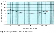
3) Here's the frequency response of the Active Equalizer from the Audio Magazine review in their November 1975 issue. Popular Electronics likewise did a review and duplicated this response. These must be early enough units that the RC network was still installed.
Active Equalizer Response Stereo Review Nov 1975.png
 

oldphaser

Chief Journeyman
Joined
Sep 8, 2012
Messages
845
#40
So ,
if I have understood well ,there are 2 versions of owner's manuals and 3 versions of
service manuals . Anyway when active equalizer is on I can hear the difference on
low frequencies . I have to use it to compensate an attenuation at 150 Hz for avoid
resonances .
Ciao
Marco

Marco,

I have 4 versions of the owner's manuals. Two from when they were in Edmonds, WA and two from when they were in Lynnwood, Washington.

I only have 2 of the 3 service manuals I am aware of. I have the 6/76 and 6/81 versions. I do not have a copy of the "fast field service manual" which pre-dated the 76 and 81 versions.

Ed
 
Last edited:
Top