phase linear 400

gene french

Veteran and General Yakker
Joined
Mar 6, 2022
Messages
5,014
Location
guayabo de bagaces, guanacaste, costa rica....
Tagline
music...the healer of souls...
Oh, I see your point. Well, from what I see, it looks like it should work at 110 VAC.
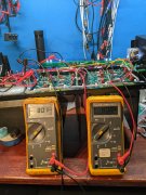
Disconnect those old caps and test the power supply section for B+ and -.
If they had a long wire disconnected from the thermo switch, and a short wire disconnected from the main fuse holder, and those two wires were connected together, then I'd say it was wired 220 VAC based on the S2 wiring graphic.
But what's up with the white wire with what may be a stripe. Looks like one goes to the buss bar, so that's the center tap. Is the other connected to the back wall or buss bar?
The S2 dual primary transformers have a single black stranded center tap wire.
The S1 standard transformers have two solid enameled wire center tap wires.
If both of those white wires go to the buss bar, your good. And of course the other two white wires are AC for the meter bulbs.
Disconnect the caps, lift those rail wires up so they don't short, and test. Your probably good.
please post that s2 schematic...
one wire out goes to one ac side of rectifier...
one wire out goes to other ac side of rectifier..
remaining wires out goes to busbar....between caps...i think windings can be configured parallel or series in output ...
i think input windings are the same...for series or parallel windings....
i think somebody tried rewiring and blew up a bunch of stuff...the wiring does not look like factory wiring ...why would ine wire be under a cap???
 

George S.

Veteran and General Yakker
Joined
Feb 18, 2020
Messages
4,539
Looks like 4 blackish blue are primaries and properly wired. Then there are the 2 white accessory wires also properly wired.
That leaves 4 white wires. 2 go to to rectifier, which looks properly wired.
That leaves 2 white wires, which I assume are center tap wires and should go to the buss bar.
With the caps installed I can't see if they are connected to the buss bar. If they aren't, you can verify the secondary windings with resistance checks.
Use that S2 transformer graphic to understand the nature of the secondary. They moved from 2 center tap wires to 1 on the later transformers.
 
Last edited:

gene french

Veteran and General Yakker
Joined
Mar 6, 2022
Messages
5,014
Location
guayabo de bagaces, guanacaste, costa rica....
Tagline
music...the healer of souls...
yes...two go to buss bar...
i will study your transformer pic..
what makes sense to me...
2 120v primary windings...twp wires per winding...in series is for 220v input....in parallel is for 120v input...
output would be similar...if you change input wiring...secondary must also change to accomodate input voltage change...
shouldnt the ac input fuse be different...halved in 220 mode?? i would think so...rail fuses would remain constant....i see labels on ends of wires...i will take pics...relabel original positions ...
start from scratch...i have an open 8fin waiting in caps to compare...
thank you so much for helping..mr. george
 

George S.

Veteran and General Yakker
Joined
Feb 18, 2020
Messages
4,539
Just use the rated fuse for US operation. Then test rail voltage at the ring terminals with the caps disconnected. If not + and - 80 VDC, then perhaps a rectifier diode is blown, or perhaps it is a wiring issue. But I don't think you have a wiring issue before the caps. Everything looks good if those two wires are center taps to the buss bar.
To convert it to 220 VAC, you'd simply take one long black bluish wire off the thermal breaker, one short black bluish wire off the main fuse holder, and connect them together in series like you stated.
Note that nothing gets changed on the secondary/center tap side.
Page 5 on the following 700 S2 manual, sorry only manual I have on phone but typical graphic in every good Series 2 manual, some don't show it.
 

Attachments

gene french

Veteran and General Yakker
Joined
Mar 6, 2022
Messages
5,014
Location
guayabo de bagaces, guanacaste, costa rica....
Tagline
music...the healer of souls...
Just use the rated fuse for US operation. Then test rail voltage at the ring terminals with the caps disconnected. If not + and - 80 VDC, then perhaps a rectifier diode is blown, or perhaps it is a wiring issue. But I don't think you have a wiring issue before the caps. Everything looks good if those two wires are center taps to the buss bar.
To convert it to 220 VAC, you'd simply take one long black bluish wire off the thermal breaker, one short black bluish wire off the main fuse holder, and connect them together in series like you stated.
Note that nothing gets changed on the secondary/center tap side.
Page 5 on the following 700 S2 manual, sorry only manual I have on phone but typical graphic in every good Series 2 manual, some don't show it.
beginning to make more sense...
 

gene french

Veteran and General Yakker
Joined
Mar 6, 2022
Messages
5,014
Location
guayabo de bagaces, guanacaste, costa rica....
Tagline
music...the healer of souls...
ok....got out the magnifying glass....
i found faded stickers on the wires....input side labeled one through four....
with the caps disconnected but the rectifier still in circuit...

wires labeled one and two are one winding...120v....three and four are the other winding 120v....i ohmed these out...
wired in parallel....wires one and three are together on one pin on the thermal switch
wires two and four are on the ring of the fuse holder for incoming voltage from shore power...
that is the 120 configuration....makes sense....and i understand...

on the output side....wires 5 through 8....
wires labeled 5 and 6 are one winding ....58 volts ac....
7 and 8 are the other winding also.... 58 volts ac....i also ohmed these out also...
this would be the configuration for the two windings wired in series....
on the plus side of the rectifier....57 volts dc...
on the negative side of the rectifier....-57 volts dc....
matches my other 8 fin voltages....
i must conclude that it is wired correctly and the rectifier seems to be operational....for 120 volts along with the american style 120 wall plug...

for the 220 config wires two and three would be wired together alone on the input side...
and i believe the output side wired five and seven together and six and eight together for the ac components of the rectifier....
a parallel configuration....thus preventing the voltage from doubling when the primary is wired for 220v ac...
this makes sense....well, it does to me....lol

now to measure the caps....put in circuit....without connecting the driver board or back plane.....
and see if the voltage approaches + and - 80 volts dc....not too worried about it....new caps here next week....
should be ready to test out when the bias transistors arrive....maybe end of next week....
should be interesting....and a lot of fun!!!

i sure learned a lot on this one....glad i investigated....because of the severe board damage....
it has been rewired since the transformer default was 240 as noted by the sticker on the caps....

i will rerun the wire that was routed under the cap....so it looks somewhat factory installed....

thanks for the boost mr. george....
 

George S.

Veteran and General Yakker
Joined
Feb 18, 2020
Messages
4,539
And Gene, you don't need the caps installed to test the transformer and rectifier for B+ and B- rail voltage. Here's a old photo with the DMM ground leads connected to the buss bar, positive leads connected to the ring terminals. Plus and minus 80 VDC clearly shown and no caps.
Those S1 transformers were wound slightly hotter than the S 2's.
 

Attachments

gene french

Veteran and General Yakker
Joined
Mar 6, 2022
Messages
5,014
Location
guayabo de bagaces, guanacaste, costa rica....
Tagline
music...the healer of souls...
i checked the transformer with all out of circuit...
i checked rectifier with caps out of circuit...
i checked caps in circuit...
transformer 58v ac
rectifier 57v dc
caps 83v dc
good to go...
got the dcprotect board installed...
just waiting on more bias transistors...
both are bad....and i only have one...
all in good time...
i have plenty to do...
thank you kind sir...
 

gene french

Veteran and General Yakker
Joined
Mar 6, 2022
Messages
5,014
Location
guayabo de bagaces, guanacaste, costa rica....
Tagline
music...the healer of souls...
maybe somebody is willing to share an opinion....or help....
this is the last 400 i purchased with the dual voltage transformer....
it had a lot of pl14 damage....and one shorted output....
both bias transistors tested bad....
i got nos bias transistors in yesterday....
after installing and double checking....
things are still not right...
i am open to suggestions...
i show rail voltage on the left channel....
right channels checks out ok....
with the left output disconnected from the dcp board....the relay engages...led lites up...
the dbt has always lit up....and faded out....as normal....but still has dc on left channel....
i removed left channel one row at a time...no change....
with no drivers and or transistors in the left side....it still shows rail on the left side....
and the dbt goes dim....and the dcp board relay engages as long as the left channel is disconnected from the protect board...
ideas??
 

George S.

Veteran and General Yakker
Joined
Feb 18, 2020
Messages
4,539
So with all the left channel outputs removed, rail voltage is making it's way to the speaker jacks from the control board. I'd suspect a bad diode or transistor on the control board.
Should be traceable using a schematic. Don't neglect doing comparison testing between similar components for each channel.
I'd personally unsolder all the control board connections to the amp and test each component on the board. Anything suspect like a diode, I'd lift one leg and retest.
Take plenty of photos before unsoldering the wiring, and then verify each connection is correct with schematic and photos before resoldering. They could have attached a broken wire incorrectly.
 

George S.

Veteran and General Yakker
Joined
Feb 18, 2020
Messages
4,539
Gene, they may have been "Wounded Soldiers" as Joe puts it, then failed as you brought it up. Good job. Hope she sings pretty!
 

gene french

Veteran and General Yakker
Joined
Mar 6, 2022
Messages
5,014
Location
guayabo de bagaces, guanacaste, costa rica....
Tagline
music...the healer of souls...
that did not clear the dc from the left channel....
however....the b+ cap has a red wire going to the back plane( b+)....and a small red wire going to the control board (b+)...
the big red wire is routed through the b+ fuse....the small red wire is not....
i removed the fuse....and powered on dbt....bright then dim....as normal...
i got rail voltage on the control board at the small red wire connection....
and no dc on the output when no b+ supplied to the back plane....yet if it is supplied to the control board....i do believe that shows that the rail voltage is not passing from the control board....to quote keb mo.....am i wrong???
and the left back planes are void of transistors....right channel fully populated....
there has to be something shorted on the back plane??
i guess i could duplicate this test for the b-??
 

George S.

Veteran and General Yakker
Joined
Feb 18, 2020
Messages
4,539
Hmm. I promptly gutted all my amps before WOPLing them, so I'm no further help.
If it were me, I'd open up a working similar amp(you have a bunch) that has the same control board and configure the problem amp to match.
Don't let that export transformer throw you. As long as B+ and B- rail voltages are correct, your good with that wiring. Working, later!
 

George S.

Veteran and General Yakker
Joined
Feb 18, 2020
Messages
4,539
Thought. There may additional "legacy" wiring in there from when it was wired for 220 VAC. Maybe that's why it was blown up. Compare it to a working amp.
 
Top