Phase Linear 200 rebuild

This is an original model, rated at 100 watts/channel that cannot reliably drive load impedances below 8 ohms.

Hi Dan
Make sure that thermal conduction strap is in good physical contact with those bias diodes to avoid the dreaded thermal runaway. The setup in that original PL200 is rather sketchy.
 
Looking at the photos of the PL-200 you did. Were those transistors substitutes for the original series or for something later?


Subs for a series II FULL COMP setup. A friend used these part numbers and did a bunch of testing. Your boards look nothing like mine.
 
Hi Dan
Make sure that thermal conduction strap is in good physical contact with those bias diodes to avoid the dreaded thermal runaway. The setup in that original PL200 is rather sketchy.
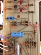
Thank you sir. I had replaced the thermal grease on the brackets and realigned it to ensure contact.

Indeed the setup is sketchy, as are the docs and my test bench... A perfect match!!!!
 
Late last night, I realized I had performed a measurement improperly and went to redo it. The measurement I had procedurally erred on was the DC from the outputs.

(For those, playing along at home, I have included reference designators)

I had forgotten to manually close the speaker protection relay. I also noted I was seeing no activity from the LED displays. I changed the Display Range switch setting on the rear of the unit which bridged the series-connect 220 ohm resistors feeding the board [R34 for the Left and R66 for the Right - (I replaced R66 when I saw it charcoaled before). When I changed the switch setting, one pair of the parallel connected 220 ohm resistors next in line (R35 and R36) overheated and changed color. I quickly shut down the power. I measured them and they have not changed in value, but they will be replaced anyway, as will the 820 ohm resistors that follow them (R37 and R38), which also look slightly discolored. Nothing else appeared to get hot.

Today, I repeated the output DC measurement (Closing the speaker protect relay with a wooden rod) and got +152mV of the left and +6 to +7 mV on the right. There is obviously DC coming from somewhere... The saga continues.2939F89A-B568-48C8-9B7F-75BC9E77A555.jpeg
 
Last edited:
Excessive Dc offset usually comes from Q1, Q2, Q3, Q4
Q1, and Q2 are a differential input, and Q3 is a voltage gain stage, if I am reading the schematic correctly. I will probably need to remove the drivers and the outputs I just installed and poke around upstream.
 
No....DBT is dim right?

I'm confused about your "No" response. Is it in reference to my circuit analysis my proposed course of action, or both?

Yes, The DBT is not illuminating and there is no high current drain from the AC mains. The load in the DBT is a 150 W flood light. The mains current draw is still around 3 mA.
 
Last edited:
Okay, I was trying to minimize the probability of them failing while I attempt to probe the front part of the amp.

I am aware of that “Velocity Fredback” circuit, from the schematic and a small description in the service manual. I realize that removing the output transistors will effect that, and remove the load from the pre-drivers as well he inputs from as the other parts of the circuit that are tied to them, including the controls for that speaker protection relay.
 
Well then, you know more about that circuit than I do...seriously....if you have a transistor that can measure gain youcan check q1 thru q4,if not they are pretty cheap transistors...
 
This amp being designed with budget in mind only has 2 transistors in the front end vs 4 for 400/700. They saved the cost of a transistor and used diodes for the bias circuit which was a bad move. The schematic is hard to read as apparently there was a paper shortage so everything was crammed on to one sheet.

In this case a precision loadbank is probably secondary to having some kind of load bank. Home depot sells a 3500 watt/240 volt water heater element for $10. The numbers work out to 16.4 ohms. Of course it's only rated for 3500 watts if immersed in water. It's not perfect but if the goal is pass/fail a loadbank can be had fairly cheap before Amazon could deliver. A 5500 watt heater is $18 which is 10.7 ohms.
 
Maybe it is just me, but I would be hacking and whacking on that circuit design. They put the summer intern on that one it appears without any supervision.
 
Maybe it is just me, but I would be hacking and whacking on that circuit design. They put the summer intern on that one it appears without any supervision.

Do it Joe.... I got the test mule.

I started to rework the board design but abandoned it about a year ago.
 
Maybe Ed knows how many of those original 200s were built in order to gauge whether is is worth it or not.

I'll bet most of them ended up in landfills. I'm a bit too hardheaded to put this one there in spite of it being a PITA, down to the connections on the power supply caps.
 
Back
Top