kl0neMan
Journeyman
Did these ever get uploaded?Phase Linear 200/200B Series 1 Amplifier Service Bulletins
Perry,
Here are just a couple of the service bulletins that were issued for the Phase Linear 200/200B series 1 amplifiers.
Time permitting, I will scan a few other 200 series 1 documents which may not have been issued as service bulletins and/or were not included in the service manuals. These would include:
1.) "FINAL ASSY & SCHEMATICS 200 AMPLIFIER 402570 E VERSION"
2.) "01 ASSY, 200 POWER AMP, P.C.B PL19 65502 DWG. NO. 402555 REV NEW"
3.) "01 ASSY, 200 POWER AMP. P.C.B. PL19 23512 DWG. NO. 402555 REV D"
4.) "01 ASSY DISPLAY BOARD PL 24 60503 DWG. NO. 402558 REV NEW"
5.) "01 ASSY DISPLAY BOARD PL24 60503 DWG. NO. 402558 REV A"
6.) "PCB ASSY. SCHEM. RELAY CONTROL 200B PL31 DWG. NO. 210-0087-0 REV A"
7.) "RELAY CONTROL ASSEMBLY 200B PL31 DWG. NO. REV A"
There are a few others as well.
Ed
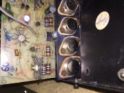
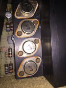
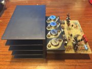
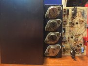
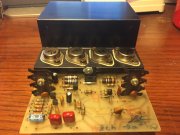
I am attempting to resurrect a PL200 (original version), that has apparently been worked on before.
So far I've found the following failed devices on the same channel using a bench multimeter for basic resistance checks:
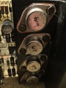
1 of 2 RCA410,
1 of 2 RCA 66430
a pair of 1N4148s that were obvioulsy in series, and
a Motorola ST258 (in the same location as an RCA 66429 on the other channel.
I believe the ST258 to be Q3 on the schematic for the original version of the 200, that I found online.
Using the same method the following devices appear to be okay:
The MPSA93s at the input (Q1, Q2)
the TIS97 (Q4),
the GES 93 (Q5),
One I believe to be 1C13 (Q6 which seems to be marked as Motorola M613 S1444), and
One I believe to be 1C12 (Q7 which seems to be marked as Motorola M613 S1443).
The 1N4004 doides used throughout.
The other 1N4148 diodes.
The .68 Ohm and .1 Ohm resistors feeding the RCA410s and the RCA66430s.
Various other resistors, (spot checking).
I had to remove some of the devices from the circuit to reliably test them.
I replaced all the electrolytic caps on the amplifier PCB other than the 1uF/80V part because I do not have a replacement yet. The 100 uF 6.3V part visibly did not olook suspect, but the 47 uF 50V part appeared swollen on both the top and underneath at the seal.
I have replaced the both RCA 410's with Motorola MJ410's. I do not have a sub for the 66430s, and am unsure what to replace them with.
I understand this model has stability problems at high frequency and low impedance. and suspect this may be the reason for a prior failure. I read the service bulletin and see a 10 PF cap across Q1 and a 22 PF across Q3 on both channels. What is the recommended course of action with respect to replacing the other transisitors, and safely bringing the amp back up? ( Using a variac, DBT, etc) while looking for oscillation on the output. I would like to have more success than whoever worked on this before.
Thanks in advance,
Dan

