Onix CD-1----Play, no tray

laatsch55

Administrator,
Staff member
Joined
Jan 14, 2011
Messages
75,065
Location
Gillette, Wyo.
Tagline
Halfbiass...Electron Herder and Backass Woof
#3
LMOAO< Joe what jumped in my mind wasn't even close!! But , no sir, I do not. Don't even know what they are.
 

Gepetto

Administrator
Staff member
Joined
May 15, 2011
Messages
14,107
Location
Sterling, MA
Tagline
Old 'Arn Enthusiast
#4
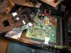
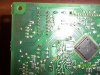
I think that the tray drive IC logic would be on the board that is attached to the bottom of the drive itself. Probably a surface mount device, that would be my guess. The TDA7073 you have pictured is a dual channel amplifier.
 

laatsch55

Administrator,
Staff member
Joined
Jan 14, 2011
Messages
75,065
Location
Gillette, Wyo.
Tagline
Halfbiass...Electron Herder and Backass Woof
#5
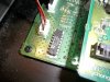
The 2 wires that run the tray and tray position switch leave the transport unmolested by way of the 4 wire harness. I will show the bottom of the board where the harness plugs intom in the next post.
 

Attachments

Gepetto

Administrator
Staff member
Joined
May 15, 2011
Messages
14,107
Location
Sterling, MA
Tagline
Old 'Arn Enthusiast
#6
420 is gone Lee so it isn't one of those clips. This is a pic of a dip clip.[attachment=0:1o5xbbzv]dip clip.jpg[/attachment:1o5xbbzv]
 

Attachments

Gepetto

Administrator
Staff member
Joined
May 15, 2011
Messages
14,107
Location
Sterling, MA
Tagline
Old 'Arn Enthusiast
#7
OK do the gray and red wire in that 4 pin connector trace to the TDA7073 on the main board?
 

Gepetto

Administrator
Staff member
Joined
May 15, 2011
Messages
14,107
Location
Sterling, MA
Tagline
Old 'Arn Enthusiast
#8
traces will be on the bottom of the board since the top is totally covered by thieving...
 

Gepetto

Administrator
Staff member
Joined
May 15, 2011
Messages
14,107
Location
Sterling, MA
Tagline
Old 'Arn Enthusiast
#10
looks like you may have to lift the main board to find out where those two wires end up getting driven by. It could be the TDA but it is an unusual application for that IC.
 

Gepetto

Administrator
Staff member
Joined
May 15, 2011
Messages
14,107
Location
Sterling, MA
Tagline
Old 'Arn Enthusiast
#12
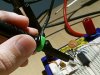
OK pins 9 and 12 are driving the motor, I agree to that. When you scope pin 9 and 12 and attempt hit the drawer open button is there any activity on pins 9 and 12? One should go high and the other one low.
 

Gepetto

Administrator
Staff member
Joined
May 15, 2011
Messages
14,107
Location
Sterling, MA
Tagline
Old 'Arn Enthusiast
#14
thieving is a PCB term, it is the copper pattern on the topside of the board. They do that to improve yield in the PCB fab process.
 

Gepetto

Administrator
Staff member
Joined
May 15, 2011
Messages
14,107
Location
Sterling, MA
Tagline
Old 'Arn Enthusiast
#16
your oscilloscope Lee. Pull the tip of the scope probe off and it will have a pointed probe tip which will allow you to get into tight places
 

Gepetto

Administrator
Staff member
Joined
May 15, 2011
Messages
14,107
Location
Sterling, MA
Tagline
Old 'Arn Enthusiast
#18
You need to find out what is going on on pin 9 and 12 of that IC

If no action there then you need to see what is happening on pins 6 and 7 which are the inputs to that driver IC
 

Gepetto

Administrator
Staff member
Joined
May 15, 2011
Messages
14,107
Location
Sterling, MA
Tagline
Old 'Arn Enthusiast
#19
set your scope up on DC input and the 5V/div scale to look at pins 9 and 12, set triggering to auto mode for constant tracing.
 
Top