- Joined
- Jan 14, 2011
- Messages
- 75,876
- Location
- Gillette, Wyo.
- Tagline
- Halfbiass...Electron Herder and Backass Woof
Done that many times George. Good advice.
Last edited:

Yeah, I got it down to pretty much all WIMA, but it bothered me that some of the leads were really angled. Then I started reading and Panasonic ECW seemed to be the best solution.Yep, those little WIMA's are a bitch to get in there..
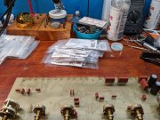
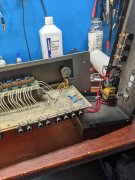
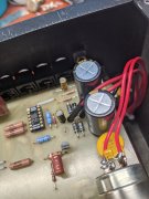
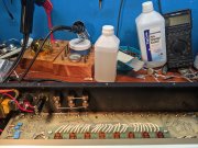
Joe makes very valid points about the quality of the original jacks. Wish there is a superb quality 90 degree replacement jack, but there isn't. I find originals adequate for my needs, particularly when servicing the unit. The first photo shows a good reason to keep the original jacks, and long wiring for the secondaries and power switch. No wiring was undone in the first photo.
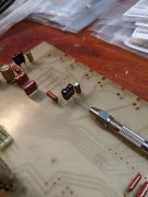
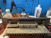
The second photo shows my attempt to strengthen the rear edge of the board with a long length of solid copper ground wire I purchased at the local big box hardware store long ago. I don't remember the gauge, but it was the smallest gauge they sold off a spool. The "star ground" is the very right side screw hole by the transformer, the middle screw has no trace to it, the far left screw hole has the trace cut away from it with a sharp counter sink bit. That far left screw gets a nylon washer under the head.
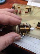
Nope, they are 90 degree phono jacks soldered directly to the circuit board. I like your idea though. In this case there just really isn't enough room to mount jacks on a intermediate plate. Very tight.
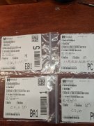
Thanks for this info.Probably easier to photo the numbers for you.
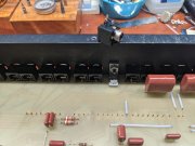
What are the reference designators on those caps that were unhappy?Mark L. , All 3 PL2000s I have are S2. The metal plate your talking about may be the transformer shield that is held in by two rear screws or the switch plate that holds the switches and is held in by the balance and reverb pot. The switch plate is 90 degree angled and is the filler for that cutout on the S2 faceplate.
As for the two film caps in the power supply. I think the reverb opamp became unstable and was creating distortion. Some thing wasn't right, and those two caps were the only difference between the two units.
Wish I knew more about electronics, but I don't. I could never have gotten these preamps to this level without the good people on this forum