Supertramp was some Excellently recorded and engineered stuff...
Agreed Lee, Crime of the Century is primo.

Supertramp was some Excellently recorded and engineered stuff...
Another of my favorites Lee.Supertramp was some Excellently recorded and engineered stuff...
Yep my favorite song I think by them.Agreed Lee, Crime of the Century is primo.
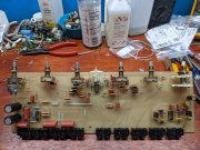
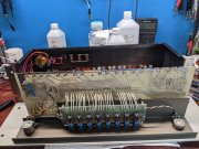
#1 is being a BITCH. 119 VAC line voltage. With no opamps installed had 40 VDC between opamps V+ and V-. Installed the original opamps to see if voltage would drop. Dropped to appx 38 VDC. Started adding resistance, 47 ohms on each secondary got each leg down to 15 VDC and change, total appx 31 VDC, so good.
Took it down to test in system just to see if any glaring issues before feeding it a 2 kHz sine wave and checking all functions on scope.
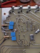
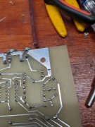
Right channel had low output, so started swapping cables and narrowed it down to the right output jack.
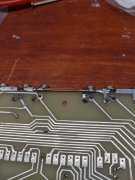
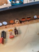
Pulled the jack and the insides were all broken. Crap! Pulled every jack, and 9 of the 18 are trashed.
Lee, now I have learned why you installed different jacks on the DeChristie preamp.
Now to find some replacements!
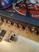
Wondered the same thingDo we have a part number for the aforementioned Switchcraft right angle RCA jacks as used in the PL2000 to replace the original RCA jacks?
Agreed Lee, Crime of the Century is primo.
Bloody Well Right!