No more 60 Hz hum in a PL2000 preamp.

Joe, I'm on the road working this week. Been thinking about this issue all morning after Mark brought it up.
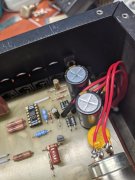
So I think the opamps were oscillating with film caps in those two positions in the photo. C44 and C26 if I remember correctly, I'm on my phone. But, I also found my phono Browndog opamp was blown, from static or the oscillations I don't know.
So the question is, did the film caps cause the oscillations, or was it the blown Browndog that was oscillating.
I need to look into this and this will be my weeks homework assignment.
This weekend I'll put original opamps in the test rig and go from there.
Thanks!
 
I'll revisit the cap issue this coming weekend. In the meantime I'll draw out the schematic, read up on where electrolytics or films are used and why.
From what I remember, C44 in the test unit was originally a weird translucent axial Sprague, I'm guessing a mylar. The original C44 caps in #1 and #2 were electrolytic axial.
 
C44 should not care if you use a film cap in that location as long as the value is equivalent. Still looking for C26
 
Joe, the other was C24, sits on the board right to the left of the rectifier filter caps. Thank you for looking!
 
Joe, this is a photo from the other day after I replaced the 2 film with electrolytics. C44 is top left and C24 is bottom left.
 

Attachments

  • PXL_20211004_174448011.jpg
    PXL_20211004_174448011.jpg
    1.9 MB · Views: 10
Joe, this is a photo from the other day after I replaced the 2 film with electrolytics. C44 is top left and C24 is bottom left.
I was looking for C26 per your earlier note. I found C24. It should not matter if film either. Neither have any effect on the stability of an op amp.

What values did you use? C44 is 1uF and C24 is 0.22uF according to the schematic.
 
Joe, know I used 1 uF for C44 and 4.7 uF for C24 per the Series 2 schematic. The Series 1 schematic shows C24 as 2.2 uF.
All 3 preamps are Series 2.
Unless your just totally bored with nothing better to do, I'll draw those S1 and S2 schematic sections out on paper from my phone this evening and try to deduce if they made a error on the S2 schematic.
I built these with values directly from the S2 schematics after measuring original resistor values on the test unit being quite a bit off from said schematic. All capacitor values I selected are also off the schematic.
If you don't see a issue with a 4.7 uF film in C24, I'll retest it. Think I also have some 2.2 uF to try.
 
Joe, I need to go back in and check all the resistor values around Q1 and Z2 opamp. Will do it this coming Sunday or Monday. Thank you SIR!
 
Interesting, looks like Q1 can be pulled disabling the Z2 opamp, and those C44 and C24 caps, it's all part of the rear channel reverb system. Think what I was hearing was oscillations of the reverb opamp. Later.
 
Joe, know I used 1 uF for C44 and 4.7 uF for C24 per the Series 2 schematic. The Series 1 schematic shows C24 as 2.2 uF.
All 3 preamps are Series 2.
Unless your just totally bored with nothing better to do, I'll draw those S1 and S2 schematic sections out on paper from my phone this evening and try to deduce if they made a error on the S2 schematic.
I built these with values directly from the S2 schematics after measuring original resistor values on the test unit being quite a bit off from said schematic. All capacitor values I selected are also off the schematic.
If you don't see a issue with a 4.7 uF film in C24, I'll retest it. Think I also have some 2.2 uF to try.
Hi George
C24 is clearly a 0.22uF film cap in the actual unit and schematic...WIN_20211005_17_11_16_Pro.jpg
 
It should not matter much at all, C24 is a coupling cap. The 0.22 in C24 location has a high pass turnover at 15 Hz.
 
Yes I have the series 2 and the value is 4.7uF polar. That circuit between the S1 and S2 is the same except for this coupling cap value. It should be non-polar for best performance. Using a 1uF film in that location will give you a 3 Hz high pass characteristic.
 
C24 is clearly a 0.22uF film cap in the actual unit
PL2000 C24.jpg

My Series 1 schematic does call out a .22uF cap for the C24 position, so I have a conflict. I'll need to find a .22uF film cap with long legs to fit in my PL2000. George, did you put a Panasonic .22uF film cap in that location?
 
Last edited:
Because we are discussing PL2000 schematic issues, do any of your PL2000 preamps have this mod? According to the schematic, the additional 33pF cap and 100 Ohm resistor were added to the back of the circuit board. Does it cure an oscillation? Cancel some 60 Hz noise?
PL2000 Schematic Mod.jpg
 
View attachment 54898

My Series 1 schematic does call out a .22uF cap for the C24 position, so I have a conflict. I'll need to find a .22uF film cap with long legs to fit in my PL2000. George, did you put a Panasonic .22uF film cap in that location?
Mark L, I built mine per the S2 schematic. That 1/50 and 4.7/30 are the issue. Yes, I put Panasonic ECW films in those two locations. I am away from home working for the week, but plan on checking a few things and trying again next weekend. Thanks for the photo.
 
O.K., so I now have films in C24 and C44 and everything is good. I really don't understand the issue I was having. Perhaps the blown phono Browndog was the issue or the fact that I didn't have the self shorting phono jacks installed.
Anyhow, #1 is done. Now going to borrow some parts out of the test unit and finish #2.
 

Attachments

  • PXL_20211010_145954619.jpg
    PXL_20211010_145954619.jpg
    2.2 MB · Views: 13
Back
Top