You are using an out of date browser. It may not display this or other websites correctly.
You should upgrade or use an alternative browser.
You should upgrade or use an alternative browser.
My WOPL 700 Containment Thread
- Thread starter mr_rye89
- Start date
mr_rye89
Veteran and General Yakker
- Joined
- Jan 14, 2011
- Messages
- 75,829
- Location
- Gillette, Wyo.
- Tagline
- Halfbiass...Electron Herder and Backass Woof
GET IT KYLE!!!
mr_rye89
Veteran and General Yakker
mr_rye89
Veteran and General Yakker
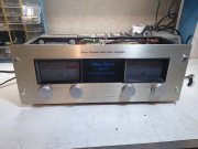
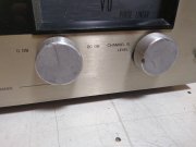
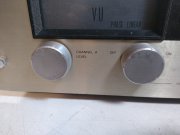
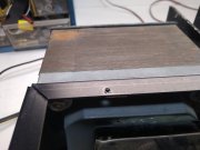
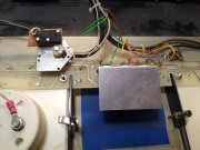
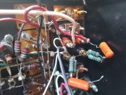
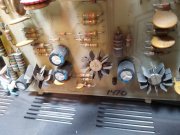
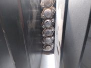
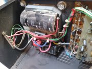
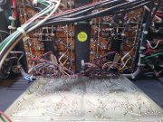
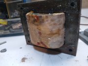
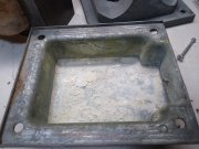
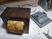
One owner from a smoke free, pet free home...we know you love a project Kyle.Aaaaannnd a moldy tranny full of white shit. No comment..
View attachment 81057
View attachment 81058
I'll be in the hot tub with a beer if anyone needs me
mr_rye89
Veteran and General Yakker
Oh yeah I don't know if the nicotine glaze is visible in the photos. Welcome to Flavor Country®
mr_rye89
Veteran and General Yakker
J!m
Veteran and General Yakker
Nice trannie...
mr_rye89
Veteran and General Yakker
She's a big 'un.....
mr_rye89
Veteran and General Yakker
J!m
Veteran and General Yakker
JBL did okay over the years but never heard of brociner.
mr_rye89
Veteran and General Yakker
Bob Boyer
Veteran and General Yakker
She's a big 'un.....
Sure it's not a Shim?
mr_rye89
Veteran and General Yakker
Sure it's not a Shim?
Good point, assuming its gender might cause a scene......
mr_rye89
Veteran and General Yakker
wattsabundant
Chief Journeyman
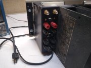
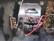
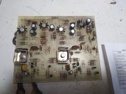
Ugh! The photos show the output binding posts were replaced with gold plated versions. That's OK, but the chassis had to be drilled to accommodate them. The studs on the new posts are larger than the standoffs (4-40) supplied for mounting the board to the OEM Switchcraft binding posts. An option would be to drill and tap one end of the standoffs to the same size as the new binding post studs.
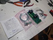
Post number 13 shows the relay board and hardware. On the left side is the AC power triac board designed specifically for the 700's. The early 700B's used an undersized Arrow Hart power switch. They were failure prone and today are nearly impossible to find. The triac board becomes the main power switch. The existing power switch controls the triac. The board mounts against the chassis and uses the existing screw that supports the driver board.
Post number 13 shows the relay board and hardware. On the left side is the AC power triac board designed specifically for the 700's. The early 700B's used an undersized Arrow Hart power switch. They were failure prone and today are nearly impossible to find. The triac board becomes the main power switch. The existing power switch controls the triac. The board mounts against the chassis and uses the existing screw that supports the driver board.
mr_rye89
Veteran and General Yakker
I bought a new chassis because the original one is junk. Everything should fit I think. Last one I did was a 4 fin PL400 and I did have to drill some extra holes.....
Since you purchased the new chassis, you can revert to the original binding posts that were installed.I bought a new chassis because the original one is junk. Everything should fit I think. Last one I did was a 4 fin PL400 and I did have to drill some extra holes.....
mr_rye89
Veteran and General Yakker
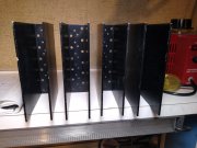
All the WOPL goodies are here. I painted the tranny and meter frames. The new light board dropped in nicely. No soldering tonight as I'm two beers in and blaring Commander Cody.....
That new chassis is really damn nice, pics later.....
That new chassis is really damn nice, pics later.....

