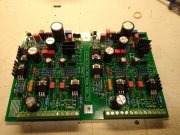
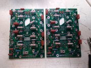
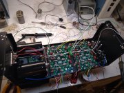
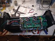
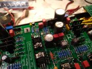
Told you Kyle...enjoy the projectAll the WOPL goodies are here. I painted the tranny and meter frames. The new light board dropped in nicely. No soldering tonight as I'm two beers in and blaring Commander Cody.....
That new chassis is really damn nice, pics later.....
You are using an out of date browser. It may not display this or other websites correctly.
You should upgrade or use an alternative browser.
You should upgrade or use an alternative browser.
My WOPL 700 Containment Thread
- Thread starter mr_rye89
- Start date
J!m
Veteran and General Yakker
Like restoring a Land Rover on a new frame.
built on stone, not sand.
built on stone, not sand.
mr_rye89
Veteran and General Yakker
- Joined
- Jan 14, 2011
- Messages
- 75,906
- Location
- Gillette, Wyo.
- Tagline
- Halfbiass...Electron Herder and Backass Woof
Late night and complete control board. I'll scrub the back in the mornin'View attachment 81432
Lookin good Kyle
.
mr_rye89
Veteran and General Yakker
- Joined
- Jan 14, 2011
- Messages
- 75,906
- Location
- Gillette, Wyo.
- Tagline
- Halfbiass...Electron Herder and Backass Woof
Excellent!!
mr_rye89
Veteran and General Yakker
Okay stupid question time, I ordered Switchcraft 3501FRX RCA jacks and they don't fit. What fits?
RCA Phono Jack - Red Switchcraft BPJR02AUXOkay stupid question time, I ordered Switchcraft 3501FRX RCA jacks and they don't fit. What fits?
RCA Phono Jack - White Switchcraft BPJR03AUX
These are the gold plated versions, I use these on the Model ONE and are the same as on original PL amps except they did not use the gold plated versions.
mr_rye89
Veteran and General Yakker
Vintage 700b
Chief Journeyman
Looking good Kyle ! 
mlucitt
Veteran and General Yakker
Kyle,
Use another pair of tie-wraps on the wires that connect to the Control Board. This will help to keep them out of your way and also prevent breakage.
I find that tie-wraps about 1" from the wire ends works really well.
Use another pair of tie-wraps on the wires that connect to the Control Board. This will help to keep them out of your way and also prevent breakage.
I find that tie-wraps about 1" from the wire ends works really well.
mr_rye89
Veteran and General Yakker
mr_rye89
Veteran and General Yakker
Welp, First gaff. Bringing up on the variac/DBT, have first row installed, control board, setting bias. C11R on the control board was installed backwards, started to bulge up and make Q50R/Q51R hot. No wonder the bias won't go above 14 mv on the right. Gonna let it cool off and see if I have another 220uf/25V.......
mr_rye89
Veteran and General Yakker
mr_rye89
Veteran and General Yakker
Changed out cap (Panasonic?) and we still have bias stuck under 14mv on the right side, so something else blew. Bias adjusts fine on the left side
+-15v rails are present, no blown fuses. not sure what I smoked. I checked to see if anything else was backwards, Replacement 220uf/25v capacitor tested to spec and is installed correctly. Idon't know....
+-15v rails are present, no blown fuses. not sure what I smoked. I checked to see if anything else was backwards, Replacement 220uf/25v capacitor tested to spec and is installed correctly. Idon't know....
Last edited:
mr_rye89
Veteran and General Yakker
I'm gonna check the MPSA92 (Q1) that was near C11. The OPA134(U1) is suspect too. Should I totally unhook the left side of the board if I sub in U1 off the left side?
U1 has near nothing to do with bias Kyle...
mr_rye89
Veteran and General Yakker
U1 has near nothing to do with bias Kyle...
Ok, was suspect because it was attached to C11, turns out that was the only thing I put in backwards. All diodes and resistors in/around the bias circuit test ok. The bias is still 14mv and the pot does nothing (it tests ok) I measured at the speaker terminals, 0mv at the left channel, 56mv on the right.
This one has me stumped
You should think of the 2 things as potentially unrelated Kyle. You are assuming the backwards cap had something to do with the bias problem when it could just be a coincidence

