
You are using an out of date browser. It may not display this or other websites correctly.
You should upgrade or use an alternative browser.
You should upgrade or use an alternative browser.
My New Early Model PL400 w/ 4 Fin Heat Sink
- Thread starter punchback
- Start date


- Joined
- Jan 14, 2011
- Messages
- 75,912
- Location
- Gillette, Wyo.
- Tagline
- Halfbiass...Electron Herder and Backass Woof
Yeah, that ain't right...
PM me your address Alan and I will snail mail you a pair.
I'll be following this thread very closely--I just received my 4-fin PL400. I listened to it on my system--there's some things I really like about, like the presentation of the snare, and the drums in general. It's not a clean as my current amp, but has a very engaging sound. I will be interested to improve anything that can be improved. I guess I should start a new thread, my board looks substantially different than the Punchback board shown in an earlier post.
Attachments
PM me your address Alan and I will snail mail you a pair.
Hi Alan
I mailed you 2 empty P-straps and 2-2N5088 transistors. Looking at the 2N5088 flat with leads pointing down the pinout is E-B-C (brown-black-red).
The P-straps are slightly open. Slide in the 2N5088 transistors in the orientation that works best for your setup, clamp the P-strap fully closed and apply a small dab of instant glue to hold the transistor in place. Proceed with your installation thereafter.
The best size wire to use for the 3 lead out wires is 26 AWG as it puts less stress on the bias transistor leads which are fragile in nature.
punchback
Journeyman
- Joined
- Jan 8, 2019
- Messages
- 124
I think I'm going to rebuild the back wall. A couple of questions. What I have differs slightly from the schematic included with the narrative wiring instructions. Resistors R36&37 are 150 ohm, on the schematic, but I have 100 ohm. Assuming I rebuild it should I get the 150's?
** Regarding the resistor type. Is it OK for the .22 emitters, 10 and 150 to be metal oxide ?
** Is 5 watt enough for the emitter? I'm looking at the KOA .22 5W .
** The 10 and 150 (100 in my case) are the same size as the majority of the resistors on the original PL400C board. Is that 1/2 or 1/4 watt?
** I guess a 1N4004 is a 1N4004
Hi Alan
You are better off using 0.33 ohms for the emitter resistors. Metal oxide, not wirewound (the originals are WW) for this application. 3W is overkill. The originals are 2W. Try and get the 2% precision on these.
Use 150 in place of the 100 that you have installed now. 1/4W is sufficient for this one as is 1/2W. Use 1/2W for the 10 ohm resistor.
Both the 150 and 10 ohm should be metal film 1% types.
Hope this helps. Yes 1N4004 are not really part of the active circuit except under fault conditions.
punchback
Journeyman
- Joined
- Jan 8, 2019
- Messages
- 124
I was able to get to work on the bias transistors. I don't know if someone had worked on this unit before me or being in the 4th month of production PL was still working out the kinks. Below is what was installed in my 400. There were 2 layers of heat shrink around a MPS5172 transistor along with a little silicone. Seems like it would take a lot of heat to affect it. Next to that is the new 2N5088.


The bracket that was in there would not (edit) have held a TO92 so thanks to Joe the new 2N5088 is installed as it should be. I had to drill out the new P bracket a little so the screw would fit properly.

The bracket that was in there would not (edit) have held a TO92 so thanks to Joe the new 2N5088 is installed as it should be. I had to drill out the new P bracket a little so the screw would fit properly.
Last edited:
Looks great Alan. Nice work
punchback
Journeyman
- Joined
- Jan 8, 2019
- Messages
- 124
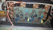
I also got in the new recommended resistors to rebuild the back wall. When I started I thought I had bit off a little more than I could chew. Removing the old resistors wasn't too difficult but cleaning up the blobs of solder was the issue. I'm not sure where I got the solder wick I had but it was not doing the job. It just would not wick up the solder very well. Luckily I live just about 25 minutes away from Parts Express. After a trip there to get some new solder wick, removing the solder was a snap. I took some pictures and labeled what was what and only worked on one column at a time. It took a few hours but I pretty happy with the results.
(edit)
For anyone choosing to do this, I had bought new MJ21196, so I could reinstalled the old PL909's to hold the TO3 sockets securely while I was working on everything.


(edit)
For anyone choosing to do this, I had bought new MJ21196, so I could reinstalled the old PL909's to hold the TO3 sockets securely while I was working on everything.
punchback
Journeyman
- Joined
- Jan 8, 2019
- Messages
- 124
I'm sure glad I got the Phoenix connectors for the PL14_20. I've had that board in and out and back in about 4 times. After rebuilding the back wall I reinstalled it once again and setup for the power up procedure. I setup the variac and DBT and flipped the switches... At about 60 VAC where I initially ran into issues there were no problems ") . When I got to about ~90 the DBT light started glowing and at ~100VAC the DCP relay kicked in
. When I got to about ~90 the DBT light started glowing and at ~100VAC the DCP relay kicked in  . I added the new MJ21196's a row at a time without any issues. After adding the last row and having no issues I went on full line voltage and everything worked fine. The bias for each channel was at about 220 mV with the pots fully CCW. I set both to about 350 mV turning each pot to about the 1:00 position. I need to re-attach the face place and get some tunes running through it.
. When I got to about ~90 the DBT light started glowing and at ~100VAC the DCP relay kicked in . I added the new MJ21196's a row at a time without any issues. After adding the last row and having no issues I went on full line voltage and everything worked fine. The bias for each channel was at about 220 mV with the pots fully CCW. I set both to about 350 mV turning each pot to about the 1:00 position. I need to re-attach the face place and get some tunes running through it.Good for another 100,000 miles Alan. Nice neat work.
I was able to get to work on the bias transistors. I don't know if someone had worked on this unit before me or being in the 4th month of production PL was still working out the kinks. Below is what was installed in my 400. There were 2 layers of heat shrink around a MPS5172 transistor along with a little silicone. Seems like it would take a lot of heat to affect it. Next to that is the new 2N5088.
View attachment 34851 View attachment 34852
The bracket that was in there would not (edit) have held a TO92 so thanks to Joe the new 2N5088 is installed as it should be. I had to drill out the new P bracket a little so the screw would fit properly.
View attachment 34853
Someone was in there before you Alan. That does not look like original work.
punchback
Journeyman
- Joined
- Jan 8, 2019
- Messages
- 124
Thanks for the kind words. When I first sat down I was wondering if this was a good idea. It got easier after each column was done.Good for another 100,000 miles Alan. Nice neat work.
So how does it sound?I'm sure glad I got the Phoenix connectors for the PL14_20. I've had that board in and out and back in about 4 times. After rebuilding the back wall I reinstalled it once again and setup for the power up procedure. I setup the variac and DBT and flipped the switches... At about 60 VAC where I initially ran into issues there were no problems