Dnspy007
Journeyman
Made a little more progress today...... Trying to keep it neat. Will tie everything together better when I install the Watts DCP. Anything I need to change before I get too far. Thanks for looking.


Nice work.
Don't forget you need to lace in two 22AWG wires to fused B- (plus a ground) to feed the Cylon meters.
See below for recently completed 400 SII with two Blue and one Black 22AWG to the left of the control board.
It's easier to add them now rather than waiting until after placing the bulk caps and tie wrapping all the wire bundles.


Cylon meters, plenty of room between the back of the meters and the cap hold down plate on this Series II build with a WO chassis...Regarding the Capacitor hold down plate. I recommend you flip it over so the notch is closer to the top of the amplifier. I had to do this on mine in order for the Meter stud to clear the hold down plate. Depending on your Meter manufacturer, it may clear regardless, but that is what the notch is for. Your build quality is excellent, you may find yourself doing these upgrades for others very soon!
Regarding the Capacitor hold down plate. I recommend you flip it over so the notch is closer to the top of the amplifier. I had to do this on mine in order for the Meter stud to clear the hold down plate. Depending on your Meter manufacturer, it may clear regardless, but that is what the notch is for. Your build quality is excellent, you may find yourself doing these upgrades for others very soon!
Never thought about the hold down plate with the all the room in a new chassis. I'll flip to make look right. Thanks againMark, Thank You for the kind words. I'm just hoping not to see Marvin before I finish..

.jpg")
The Base and Emitter pins are offset from the centerline. You can observe that when you pick one up and look at the bottomside. The backplane boards likewise have offset sockets to properly mate with this offset in the transistors. The offset is enough to be obvious. You need to be observant of this when you install them. If you put them in the wrong way, the screw holes will not line up.I've got a few questions on the Output Transistors. Never done any kind of work with them. How do you tell the correct orientation? I noticed when I took one out to look at it, There was an arrow molded in the styrofoam. Is that pointing the correct orientation?
View attachment 86843
Thanks Joe,The Base and Emitter pins are offset from the centerline. You can observe that when you pick one up and look at the bottomside. The backplane boards likewise have offset sockets to properly mate with this offset in the transistors. The offset is enough to be obvious. You need to be observant of this when you install them. If you put them in the wrong way, the screw holes will not line up.
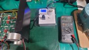
Yes, +/- 84V rail voltage with 120V AC input looks correct.Brought up the Bare Wire Chassis today.... No smoke, No shorts and no blown fuses.
Is the voltage reading about right at this stage in the build? Thanks Guys
View attachment 86892
View attachment 86893
Brought up the Bare Wire Chassis today.... No smoke, No shorts and no blown fuses.
Is the voltage reading about right at this stage in the build? Thanks Guys
View attachment 86892
View attachment 86893