Mark goes at it again... just bought a PL700/II!

MarkWComer

Veteran and General Yakker
Joined
Nov 1, 2014
Messages
3,507
Location
Gaston, SC
Tagline
Victim of the record bug since age five
Hey Mark
The special hardware kit provided with the chassis has the proper thickness nylon washers provided in it to center the S2 sub panel. The chassis is intentionally larger than the original in L x W x D to provide more space for proper alignment and spacing of components.
Apparently a detail that I neglected to read. I seem to do that a lot.
 

MarkWComer

Veteran and General Yakker
Joined
Nov 1, 2014
Messages
3,507
Location
Gaston, SC
Tagline
Victim of the record bug since age five
Love your videos Mark. I watched them all before I started my builds last year. Even ordered that PCB holder you recommended, worked great. Going to try to get my meters installed this weekend, very helpful video, thanks for your outstanding efforts. You do make a difference in this screwed up world. Thanks man!!!
Honestly, I didn’t care too much for that board holder. I bought it as a less expensive alternative to the PanaVise, and I don’t think I’d like those any better. I just lay the boards on an old washcloth.

THANKS GREATLY for the praise! I know that you have to be a true circuit geek in order not to fall asleep watching these. I learned to keep them short as possible after watching them myself (the 400 series vids are terrible!) and try my best to have some fun and jokes. Since part 16 will be the last, I’m searching for some gag props to use. Old Ernie Kovacs videos give me some ideas...
 

MarkWComer

Veteran and General Yakker
Joined
Nov 1, 2014
Messages
3,507
Location
Gaston, SC
Tagline
Victim of the record bug since age five
Mark great video! You mentioned PL does not follow their schematics at time mark 7:13. Can you share what you found to be incorrect?
What most immediately comes to mind is the change in the emitter resistors from .22 to .33Ω, but I noticed a few others grousing over a mysterious capacitor, omitted transistor, etc. I’m a lazy sod to find other gripes and complaints regarding inaccurate schematics. Perhaps I spoke too soon or without regard, but there are some undocumented revisions that pop up here and there and mentioned here in the forums. T’was a general statement without specific examples.
 

MarkWComer

Veteran and General Yakker
Joined
Nov 1, 2014
Messages
3,507
Location
Gaston, SC
Tagline
Victim of the record bug since age five
We are glad to have you back here and posting Mark. Don't be a stranger...
Amen to that Joe..
Thanks!

At least I get a response here- I post on FAKEbook with no response. They’re too busy arguing about Herr Kartoffelkopf.
(Mark Comer on FAKEbook in case you decide to track me down..)
 

mlucitt

Veteran and General Yakker
Joined
Jun 24, 2011
Messages
3,494
Location
Jacksonville, FL
Perhaps I spoke too soon or without regard, but there are some undocumented revisions
No worries, I am trying to document all the reported errors and hopefully publish them here someday. I was curious if you caught anything I missed. The change in emitter resistor values is one I missed because I thought of that as a model change, but as you point out, it was a fairly random change. I included several typos and missing values, the one that irks me the most is the random numbering of output transistors from model to model and the different ways the primary wiring is done from model to model.
 

Gepetto

Administrator
Staff member
Joined
May 15, 2011
Messages
14,037
Location
Sterling, MA
Tagline
Old 'Arn Enthusiast
No worries, I am trying to document all the reported errors and hopefully publish them here someday. I was curious if you caught anything I missed. The change in emitter resistor values is one I missed because I thought of that as a model change, but as you point out, it was a fairly random change. I included several typos and missing values, the one that irks me the most is the random numbering of output transistors from model to model and the different ways the primary wiring is done from model to model.
Probably due to all the weed smoked back in the 70s at the PL plant...
 

MarkWComer

Veteran and General Yakker
Joined
Nov 1, 2014
Messages
3,507
Location
Gaston, SC
Tagline
Victim of the record bug since age five
No worries, I am trying to document all the reported errors and hopefully publish them here someday.
Well, there is the fuse "polarity" issue, but I think you know about that one:

Power from the filter caps go to the TIPS of the fuse, power from the fuse RING goes to the guts. If they're wired in reverse and you pull a fuse with the caps charged, the bare metal from the exposed fuse holder ring is a potential shock hazard. My 700 was factory wired this way and I kept with their errant tradition. Shizzbit! It was too easy to bend the tabs of the fuse holder together and make a common connection instead of wiring the tips together. If nothing else, I'm consistent and wired the main fuses likewise. Some future technician will have his fingerprints altered!
 

v65magna

Journeyman
Joined
May 6, 2019
Messages
69
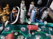
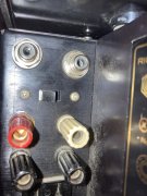
The normal mode inserts a series capacitor between the preamp and the amp to block any DC from the source. The direct mode shorts this cap out.
It’s hard to tell which way is in normal position , because of that decal is on the side of the panel so the switch to be on normal should be to the left when look at it from the back ,, is this correct , thank Peter
 

v65magna

Journeyman
Joined
May 6, 2019
Messages
69
The normal mode inserts a series capacitor between the preamp and the amp to block any DC from the source. The direct mode shorts this cap out.
Is this the normal mode , just making sure mine is on the normal position thanks any replies will 30E9A860-4AF2-4E6D-9E19-C41A1A0127E8.jpeg be appreciated
 

mlucitt

Veteran and General Yakker
Joined
Jun 24, 2011
Messages
3,494
Location
Jacksonville, FL
Is this the normal mode , just making sure mine is on the normal position thanks any replies will be appreciated
Yes, "Normal" is nearest to the Red (Right) speaker binding terminal. Look inside and make sure the switch position is lined up under the switch terminals that do not have the capacitors attached (the switch shorts out the capacitors and "directly couples" the input jacks to the Control Board).

From the Owner's Manual:
"The "normal" mode should be used for high fidelity musical reproduction. This mode provides protection for the woofer against large cone excursions caused by subsonic signals generated in the preamp at the moment of turn-on. Whereas, the "direct coupled" mode should only be used when the unit is driven as a power operational amplifier in industrial applications." Also: "CAUTION: DO NOT SWITCH MODES WHILE THE AMPLIFIER IS IN OPERATION."

If you have a DC Protect Relay Delay Board installed, you would not have to worry about the turn-on "thump". But it is not a bad idea to have a 2.2uF 25V film capacitor on the input unless you trust your preamp to never send any DC signals to the amplifier.
 

MarkWComer

Veteran and General Yakker
Joined
Nov 1, 2014
Messages
3,507
Location
Gaston, SC
Tagline
Victim of the record bug since age five
2:20... Not sleeping...

I bought a bunch of props on ebay and trying to gel two monologues for the final videos of the rebuild series. 2 1/2 years on a project that takes everyone else less than two weeks (embarrassed at that..), and I want to end it with a bang good enough to split some sides, or at least get someone to piss theirself.

Miss Speedbump of 1986 in the wings practicing her lines now...
 

MarkWComer

Veteran and General Yakker
Joined
Nov 1, 2014
Messages
3,507
Location
Gaston, SC
Tagline
Victim of the record bug since age five
So, with the 700 finished and closed up, where’s the volume? I know, it takes double the power to raise gain only 3db, but the 400 blasts with the volume 1/3 the way up. At 2/3 the way up, the 700 only starts to blast...

Rail voltages checked fine during assembly, so I don’t think it’s a power issue.

I’m gonna have to do a swap on the driver boards and see what I get. Rev. E on the 400, Rev. G on the 700.
 

Gepetto

Administrator
Staff member
Joined
May 15, 2011
Messages
14,037
Location
Sterling, MA
Tagline
Old 'Arn Enthusiast
So, with the 700 finished and closed up, where’s the volume? I know, it takes double the power to raise gain only 3db, but the 400 blasts with the volume 1/3 the way up. At 2/3 the way up, the 700 only starts to blast...

Rail voltages checked fine during assembly, so I don’t think it’s a power issue.

I’m gonna have to do a swap on the driver boards and see what I get. Rev. E on the 400, Rev. G on the 700.
Voltage gain is identical between the 400 and 700 Mark.

Rather than doing all the swaps, post some good photos of your G1 assembly.
 
Top