Made a deal on PL700 and PL4000

AngrySailor

Veteran and General Yakker
Joined
Oct 15, 2014
Messages
3,419
Tagline
---not quite right
#2
Just confirmed time and contact info with the seller. I am FINALY signing off the ship tomorrow so the timing was perfect. I’ll take them to my fathers place and build shipping crates while I visit the folks for two days then I’ll be flying back east to home base.

He said these were in service last a few months ago if I remember right. Said the 700 had caps and service about 2 years ago. Anything in particular I should look for before powering her up? Planning to use a dbt and check DC at speaker posts but otherwise? If that’s good let her loose?
 

laatsch55

Administrator,
Staff member
Joined
Jan 14, 2011
Messages
74,124
Location
Gillette, Wyo.
Tagline
Halfbiass...Electron Herder and Backass Woof
#3
Yep...try not to have a really good pair of speaks hooked to it for awhile till ya get it good and warmed up a few times..
 

AngrySailor

Veteran and General Yakker
Joined
Oct 15, 2014
Messages
3,419
Tagline
---not quite right
#4
It might "warm" anything other than really good pair of speakers before even breaking a sweat though! She is destined for subwoofer duty driving a pair of Peavey Low max 18" subs while the PL400 takes care of the rest. I might test try it at my fathers place and it wouldn't be the first time his speakers blew while I was driving, (I did repair them though). Is a DCP board available for this? How about an LED kit? I plan to take her top down and have a looksee for the replacement caps and any work done to her also. I hope she doesn't need WOPLing right now as I paid for a working amp, but I'm planning to WOPL something as a learning experience at some time soon. Electronics is becoming more important in my field of work and I've been enjoying learning more about the subject.

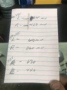
Also, what is acceptable/normal DC offset range and both channels should be positive right?
 
Last edited:

laatsch55

Administrator,
Staff member
Joined
Jan 14, 2011
Messages
74,124
Location
Gillette, Wyo.
Tagline
Halfbiass...Electron Herder and Backass Woof
#5
The DCP of Don's for a 700 will work. A driver board will work. No backplanes or lights on that one.
Offset can be positive or negative. Less than 75 mv..
 

AngrySailor

Veteran and General Yakker
Joined
Oct 15, 2014
Messages
3,419
Tagline
---not quite right
#7
60 watt bulb dimmed, checked Dc offset while on dbt
Left 64mV
Right 428mV
 

laatsch55

Administrator,
Staff member
Joined
Jan 14, 2011
Messages
74,124
Location
Gillette, Wyo.
Tagline
Halfbiass...Electron Herder and Backass Woof
#12
Should be 3 trimpots per side on the driver board. 2 are for offset per channel and the other for bias. Get a service manual, it'll make sense..

In the original 700's offset is adjustable.
 

AngrySailor

Veteran and General Yakker
Joined
Oct 15, 2014
Messages
3,419
Tagline
---not quite right
#14
Thanks. I’ll download a manual and take a look under her top. That will be for tomorrow though as I’m visiting with pops and a friend. We’re spinning some vinyl in pops’ shop and speaker lubricant is flowing. Sure is nice not having to watch a ships position so I don’t miss it!
 

oldphaser

Chief Journeyman
Joined
Sep 8, 2012
Messages
845
#19
What’s this direct/normal coupling switch. Haven’t even looked for a manual yet...
The Phase Linear 700 (Edmonds Washington version of the) owners manual states:
INPUTS
"... the Phase Linear 700 is equipped with direct coupled inputs as well as normal coupled inputs. For high fidelity reproduction, the "normal" coupled inputs are to be used. The normal inputs provided protection for the woofer against large subsonic cone excursions generated by drive from the preamp at the moment of turn-on."

"The "direct coupled inputs are to be used whenever the unit is used as a power operational amplifier in industrial applications. Referring to Figure 1, the upper two inputs are normal inputs. The lower two are the direct coupled inputs. The input selector switch must be up when using the upper inputs , and down when using the lower inputs".

Frequency response
0-.25 mHz @ 1 volt, direct coupled inputs
10-.25 mHz @ 1 volt, normal inputs


Turn-0n
Normal inputs: 500 millisecond delay prevents preamplifier subsonic signals from arriving at the moment of turn-on
Direct coupled inputs: Instantaneous


FRONT PANEL CONTROLS
"The level controls adjust the gain of the Phase Linear when using the normal inputs. They are bypassed when using the direct coupled inputs, which allow direct access to the voltage amplifier stages."

ED COMMENT: When using the direct coupled inputs on a 700, bypassing the level controls (volume pots) will also improve the signal-to-noise ratio by approx 2-3dB.

The Phase Linear 700B owner's manual has some additional verbiage at the end of the INPUTS section:
"...For direct coupled operation the input switch should be moved to the right. Correct hook-up of the 700B is also silk-screened on the heat sink. DO NOT SWITCH MODE SELECTOR WHILE THE AMPLIFIER IS IN OPERATION."

NOTE: There is also a difference in Frequency Response.
Frequency response
1-.25 mHz @ 1 volt, direct couple inputs
5-.25 mHz @ 1 volt, normal inputs


The 2/81 revision of the Phase Linear 700/700B service manual states:
"The model 700 or 700B can be operated in either the "normal" or direct coupled input modes. For high fidelity home use the unit should be operated in the NORMAL mode. This provides for AC coupling at the inputs which has a subsonic rolloff of 6dB/octave with a corner frequency of about 15Hz. This can be effective in preventing loudspeaker woofer damage from DC or subsonics passed to the amplifier for a unit "upstream" in the signal path."


"In the DIRECT coupled mode frequencies are amplified down to DC, at which there is a gain of 1. In some sound reinforcement applications it may be desirable to operate the unit in the DIRECT coupled mode."


ED COMMENT: I have seen a number of Phase Linear 700B and 700 series two amplifiers that have been modified over the last few years where the normal/direct coupled switch has been bypassed and left in place. Perhaps it would be better to install a blank piece of aluminum with machine screws to better illustrate to potential owner's that it has been bypassed.

Ed
 

oldphaser

Chief Journeyman
Joined
Sep 8, 2012
Messages
845
#20
60 watt bulb dimmed, checked Dc offset while on dbt
Left 64mV
Right 428mV
The DC offset spec in the Phase Linear 700 service manual (for serial numbers 0 thru 773-200) stated:
"using a voltmeter, adjust the offset controls so that the meter indicates 0 (zero) volts at the speaker terminals between hot and ground. The controls are readily adjusted simply by using the index finger and thumb, reaching down through the top of the amplifier. Adjust as follows:
A) Set the input mode switch to A.C. coupling.
B) Rotate the level control fully counterclockwise (level down) and adjust output offest for 0 (zero) volts.
C) Rotate level control fully clockwise and adjust input offset for 0 (zero) volts. This completes offset adjustments
.

The 6/76 revision of the 700/700B service manual stated:
Step #7 Offset: There should be not more than about +/-75 millivolts of DC voltage at the output terminals. If a unit exhibits excessive offset:
a) 700B units containing PL14 or PL20 boards, replace Q1 and Q2 if offset exceeds
+/-75 mv DC
b) 700 units containing PL0171: Switch to normal inputs, rotate volume control fully counterclockwise and zero the output offset by rotating R17. Now turn the volume control fully clockwise and zero the output offset by rotating R7. Repeat this step several times until the output offset remains zeroed at both the full clockwise and counterclockwise positions of the volume control.

The 2/81 revision of the Phase Linear 700/700B service manual stated:
Step 5-6 Offset. With no input connected to the amplifier, measure across the output terminals of each channel for presence of DC offset voltage and verify less than +/-50mV.


Step 6-6 EXCESSIVE DC OFFSET VOLTAGE
Model 700:
a) Remove all inputs to the amplifier. Monitor the offset voltage at the output of the left channel. Monitor the offset voltage at the output of the left channel. With front panel input sensitivity controls closed (fully CCW) adjust DC offset by R17 on the pc board. Then with the front panel input control open (fully CW) adjust R7 on the pc board. It may be necessary to repeat the adjustments since one will slightly affect the other. Repeat the procedure for the right channel. Offset should be less than 50mV at any level position.
b0 If DC offset cannot be zeroed (less than 50mV) using the above procedure replace differential pairs Q4/Q5 or Q2/Q3 and readjust as per the above step a).


ED COMMENT: It has been my experience with the PL0171 pc boards that the DC offset will drift as the amplifier heats and cools. Other than a 5 minute warm-up time before testing the amplifier, there is no further guidance. Subsequent pc boards used by Phase Linear did not drift as badly as the PL0171 did.
 
Top