Kevin's PL400 Upgrade

mlucitt

Veteran and General Yakker
Joined
Jun 24, 2011
Messages
3,497
Location
Jacksonville, FL
#61
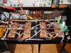
Got the wires cut to length and tinned - ready for the board.
[attachment=1:e9e5vljx]Wires Prepped.jpg[/attachment:e9e5vljx]

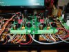
Then the board is bolted in and connected up. A few point-to-point continuity checks (like 52 of them) and then I will zip-tie it up.
[attachment=0:e9e5vljx]Board In.jpg[/attachment:e9e5vljx]
 

Attachments

kevin

Forum Veteran and Hillbilly
Joined
Dec 22, 2011
Messages
1,422
Location
Wise VA
#62
Mark. How are you connecting those terminal blocks to that board ? How many of each part number do you need for a 400 ... Sutton ask that .... Do you have to drill that board... Is that where lee said he drilled and messed up....
 

mlucitt

Veteran and General Yakker
Joined
Jun 24, 2011
Messages
3,497
Location
Jacksonville, FL
#63
Those terminal blocks solder on but you have to be careful to make sure that both the top and the bottom wire runs are making contact with the terminal block. I check each board component and terminal screw with an Ohm meter. I recently found one board with one terminal that would not conduct to the board. I had to resolder it five times before it finally flowed to the top of the board from the bottom, where I soldered it. You need two of each P/N for both the PL400 and the PL700.

The board does not need to be drilled unless you have soldered the hole close and it will not completely open up. I believe the holes that Lee and I had trouble with were the connection holes for the bias transistor Q6 on both sides. Joe said he would open the holes on the next board revision.
 

mlucitt

Veteran and General Yakker
Joined
Jun 24, 2011
Messages
3,497
Location
Jacksonville, FL
#64
Lee,
If you have found any bad outputs, what is the failure mode. Do they show direct short or do they open? I have read that these high-power outputs we use can have leakage in a test environment and look bad but under power they are fine. I have some used outputs that "leak" instead of showing infinity in the diode test.

I wish I had a curve tracer...

Thoughts?

Mark
 

laatsch55

Administrator,
Staff member
Joined
Jan 14, 2011
Messages
75,065
Location
Gillette, Wyo.
Tagline
Halfbiass...Electron Herder and Backass Woof
#65
Yep, I had also drilled 11R & L, 12 R & L, 5 R & L. I guess screwing up the bias wasn't enough fun.
 

laatsch55

Administrator,
Staff member
Joined
Jan 14, 2011
Messages
75,065
Location
Gillette, Wyo.
Tagline
Halfbiass...Electron Herder and Backass Woof
#66
The only sure way is the current sharing test. Most failures I';ve seen (90%) are shorts. It aint rocket surgery to find those. I do the diode test on all junctions and if I don't have any opens or shorts they get the chance to rock.
 

mlucitt

Veteran and General Yakker
Joined
Jun 24, 2011
Messages
3,497
Location
Jacksonville, FL
#67
Yeah. I guess all bets are off on the current sharing test if the emmitter resistors are subject to a bit of heat and 40 YEARS OLD! I'll have to find a good source of .22, .27, and .33 1W (or better yet for our purposes) 2W 5% resistors. Sheesh.
 

mlucitt

Veteran and General Yakker
Joined
Jun 24, 2011
Messages
3,497
Location
Jacksonville, FL
#69
MF or MO? Wassat? I checked Mouser and they have the Ohmite 2W .33 and .22 but no .27. So I looked for Vishay-Dale and they have the .27 but no .22 or .33 in 2W. I was able to find all three in 3W and 1%, but they are kinda expensive and the .27 are backordered...
 

mlucitt

Veteran and General Yakker
Joined
Jun 24, 2011
Messages
3,497
Location
Jacksonville, FL
#71
Funny, I made no reference to the composition. Although, I would think wirewound would be typically preferred for that application. I have no issue with metal film, though. Joe what are your thoughts?
 

Gepetto

Administrator
Staff member
Joined
May 15, 2011
Messages
14,108
Location
Sterling, MA
Tagline
Old 'Arn Enthusiast
#72
MF and MO are typically less inductive, lower noise and therefore a better resistor. WW if they are non-inductively wound (not all are) come close. WW typically have better power handling capability than MO or MF.

Doubt any of this matters to the human ear but these artifacts may show up in a subtle way on an oscilloscope. The (relatively low) frequencies we are involved with do not make WW a bad choice.
 

wattsabundant

Chief Journeyman
Joined
Apr 26, 2011
Messages
946
Location
Central Ohio
#73
I haven't been here for a while. Now I know why my ears were burning. Looking over the posts I'd like to add a few comments.

Mark, your work of routing the wires to the relay board is really nice. Believe me, I've tried, but I haven't done that good. Also I've never seen the green insulator on the bus. Is that stock?

FWIW, on the relay board there is a red dot on top of the resistor. That is my QC stamp. After I test the board I put a drop of finger nail polish there. I also put a drop on the bias pot and the threads of the driver PCB mounting studs when I do an amp.

At my day job, I teach troubleshooting classes on high power inverters. (typically 5-100KW) I do my best to convince the students that the most common failure mode of power semiconductors is a short circuit. Output transistors fall in this category. Signal transistors can be different. They can get noisey/leaky. Been there recently on a Marantz 140.

There's a service bulletin (1-80, bottom of P2) in the P/L400 service manual that mentions reports of leaky transistors when used with certain test equipment. The conclusion is do the load sharing test.

With a good ohm meter you can track down a shorted output in a P/L amp without pulling any screws. Look from C-E on the outputs. If one is shorted they all appear to be shorted. However, close observation will show that the shorted one is actually a .2 to .3 ohms lower. The emitter resistors are the difference.

Now for my rant. It' about safety. If you're working on this stuff you need to be wearing approved safety glasses at all times. You've got to work safe. At my day job I can go through 800A fuses on 1000 amp SCRs and it doesn't bother me near as much as doing the load sharing test on a 700B. The reason is my face is within a couple feet of the the amplifier and I've had them come unglued before. 400's have a 150 volt DC power supply. 700's are almost 200VDC. If you ever get across it, there's no letting loose. It's not like AC. AC turns off every 8 milliseconds. DC grabs and doesn't let go.

Everybody please be safe so you can enjoy the fruits of your labor.
 

mlucitt

Veteran and General Yakker
Joined
Jun 24, 2011
Messages
3,497
Location
Jacksonville, FL
#74
Don,
I added the Phoenix insulators on the first board I replaced because I thought I would be taking it in and out a bunch of times. I was wrong. Joe's directions and parts identification coupled with a great circuit board (we called them printed wire boards (PWB) in the Navy, were so good I never had to remove the board. I liked the idea of the terminal boards so I have continued to install them. They are Mouser P/N 651-1729128 and 651-1729209. You will need two of each.

Don, freel free to use the pictures if you like. I just think if you want to do something, you might as well do it right.

Thanks for your post.
 

Skratch

Chief Journeyman
Joined
Dec 27, 2011
Messages
1,172
Location
Huntley Il.
Tagline
Life is short, so take your time
#75
Men, I agree with Don about safety. I like the old tube stuff, and got whacked 500 volts DC and it is not a pleasure.
 

laatsch55

Administrator,
Staff member
Joined
Jan 14, 2011
Messages
75,065
Location
Gillette, Wyo.
Tagline
Halfbiass...Electron Herder and Backass Woof
#76
I was trained under an old Air Force turned oilfield electrician and everytime both hands went in a box with palms inward and it was hot, he would slap me accross the back of the head, HARD!@! And then SCREAM----" YOU ARE 100 MILES FROM NOWHERE, IT'S DARK 30, SNOW IS BLOWIN UP YOUR ASS, IT'S COLDER THAN HELL A N D Y O U C A N T M A K E T H A T M I S T A K E W H E N Y O U A R E A L O N E !!!!" I learned not because I was afraid of dying by electrocution but the back of my head was tired of getting hit. I could have taken the old man, but he was a good friend and training me up for nothing because he knew I was gonna do it anyway so he was doing what he could top keep me alive. He is still aliove to this day. Has a place in Florida where he lands his plane and taxi's to the back door, Good Man. Jim West, West Industrial Electric. Bless your heart.
 

laatsch55

Administrator,
Staff member
Joined
Jan 14, 2011
Messages
75,065
Location
Gillette, Wyo.
Tagline
Halfbiass...Electron Herder and Backass Woof
#78
Safety is relevent anywhere, anytime, as long as it's not done like they do it at a coal mine, sheesh.
 

Gibsonian

Chief Journeyman
Joined
Aug 3, 2011
Messages
856
#79
laatsch55 said:
I was trained under an old Air Force turned oilfield electrician and everytime both hands went in a box with palms inward and it was hot, he would slap me accross the back of the head, HARD!@! And then SCREAM----" YOU ARE 100 MILES FROM NOWHERE, IT'S DARK 30, SNOW IS BLOWIN UP YOUR ASS, IT'S COLDER THAN HELL A N D Y O U C A N T M A K E T H A T M I S T A K E W H E N Y O U A R E A L O N E !!!!" I learned not because I was afraid of dying by electrocution but the back of my head was tired of getting hit. I could have taken the old man, but he was a good friend and training me up for nothing because he knew I was gonna do it anyway so he was doing what he could top keep me alive. He is still aliove to this day. Has a place in Florida where he lands his plane and taxi's to the back door, Good Man. Jim West, West Industrial Electric. Bless your heart.
The many hits in the head in your past - now I understand you alot better Lee! :lol:
 
Top