Inverted back plates build

grapplesaw

Veteran and General Yakker
Joined
Aug 13, 2014
Messages
2,786
Location
Vancouver
Tagline
---
#81
Have you scoped the signal path starting at the input of the op-amps?
Thanks for idea Lee
No. I was thinking if both channels has same condiotn the cause is before that point. Some common power supply so I will try that. All what is best connect for signal out to backplates to see how it looks before being amplified?

Are there test connects for that. Or do I just go off ine imput leg if the op-amp? Looks like pin #3
 
Last edited:

laatsch55

Administrator,
Staff member
Joined
Jan 14, 2011
Messages
75,314
Location
Gillette, Wyo.
Tagline
Halfbiass...Electron Herder and Backass Woof
#82
So......it cleans up after the regulated low voltage goes below the regulated voltage. Have you checked your low voltage regulators? Could just be a coincidence, but maybe not...
 

grapplesaw

Veteran and General Yakker
Joined
Aug 13, 2014
Messages
2,786
Location
Vancouver
Tagline
---
#83
So......it cleans up after the regulated low voltage goes below the regulated voltage. Have you checked your low voltage regulators? Could just be a coincidence, but maybe not...
No
I am looking for the segantic for that. I will let you know if I do not find it
 

laatsch55

Administrator,
Staff member
Joined
Jan 14, 2011
Messages
75,314
Location
Gillette, Wyo.
Tagline
Halfbiass...Electron Herder and Backass Woof
#84
Thanks for idea Lee
No. I was thinking if both channels has same condiotn the cause is before that point. Some common power supply so I will try that. All what is best connect for signal out to backplates to see how it looks before being amplified?

Are there test connects for that. Or do I just go off ine imput leg if the op-amp? Looks like pin #3
I woukld check the outputs of the pre-drivers to see if the altered waveform is present there. The negative pre-driver, the PNP pad
 

grapplesaw

Veteran and General Yakker
Joined
Aug 13, 2014
Messages
2,786
Location
Vancouver
Tagline
---
#85
I woukld check the outputs of the pre-drivers to see if the altered waveform is present there. The negative pre-driver, the PNP pad
Right!

First check VR1&2 for out out and test for damage to either then scope PNP

I am fitting this in between my Honney do list my wife has he working on to day

Thanks for the ideas Lee
 

grapplesaw

Veteran and General Yakker
Joined
Aug 13, 2014
Messages
2,786
Location
Vancouver
Tagline
---
#87
I woukld check the outputs of the pre-drivers to see if the altered waveform is present there. The negative pre-driver, the PNP pad
same wave pattern from PNP connect
Should I disconnect from Back plate and retest or look farther up the line

Voltage reg -15.95 v and +15.270 steady
I will scope the output as well for these
 

grapplesaw

Veteran and General Yakker
Joined
Aug 13, 2014
Messages
2,786
Location
Vancouver
Tagline
---
#89
I checked in pin 1 and no distortion one step before op amp pin 3
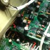
I checked op amp out pin 6 by connecting on R4 as pictured
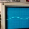
Here is wave patern, inverted from out put and PNP

I resoldered PNP and D 9 l&r back into board

Distortion starting now at a little lower voltage

So we have clean in to op amp and distorted half wave on out of op amp

Have it put something in backwards??


image.jpg image.jpg
 
Last edited:

laatsch55

Administrator,
Staff member
Joined
Jan 14, 2011
Messages
75,314
Location
Gillette, Wyo.
Tagline
Halfbiass...Electron Herder and Backass Woof
#93
If you unhooked the DC protect you no longer have a zoebel network anymore, that's probably where you are getting that "singing"...
 

grapplesaw

Veteran and General Yakker
Joined
Aug 13, 2014
Messages
2,786
Location
Vancouver
Tagline
---
#94
If you unhooked the DC protect you no longer have a zoebel network anymore, that's probably where you are getting that "singing"...
That went back together Right after I tested it. Isn't the zoebel now on the backplates ?

I am getting a little frustrated so I think wholesale changing out components may be best. I will try new caps then I will put together a pl board and swap it. Need to go back and check the bridge rectifier. I will check that the rc plunges have no ground fault.
 

laatsch55

Administrator,
Staff member
Joined
Jan 14, 2011
Messages
75,314
Location
Gillette, Wyo.
Tagline
Halfbiass...Electron Herder and Backass Woof
#97
My bad Glen, yes the Zoebel is now on the backplanes...brain fart......hangover....who knows...
 

grapplesaw

Veteran and General Yakker
Joined
Aug 13, 2014
Messages
2,786
Location
Vancouver
Tagline
---
#98
My bad Glen, yes the Zoebel is now on the backplanes...brain fart......hangover....who knows...
An old Japanese man I worked for some time ago who was intered during the Second World War gave me a saying I use often. It is good for all occasions. It's just how you say it.

When things are light and easy. Say It doesn't matter anyway
And when things are not going well. Say it doesn't matter anyway

And when you are mad . Say I dont give a dam! It doesn't matter anyway!!!


so Lee my just of it is. Anyway it doesn't matter

glen
 
Last edited:

NavLinear

Veteran and General Yakker
Joined
Apr 12, 2012
Messages
6,073
Location
SoCal
Glen,

It's conceivable that you have a bad IC. I reread this thread and you said that the signal at the input to the op amp is clean but measured at the output the signal is distorted. You've verified that the signal generator is good so you've eliminated the test equipment. If you're using a two channel oscilloscope it's nice to have the source input displayed on one channel and the measured signal in the item under test displayed simultaneously. When I'm testing a circuit this dual display is my sanity check.

Verify that the op amp is inserted correctly and if so you may want to swap the left and right channel IC's to see if the problem moves. It is quite possible that something down stream from the op amp is the culprit but this is a quick check. Of course make sure the reservoir caps have bled off.
 
Top