I'm Buying a "Mule" PL400

mlucitt

Veteran and General Yakker
Joined
Jun 24, 2011
Messages
3,375
Location
Jacksonville, FL
Has anyone else converted a quasi configured Rev E Control Board in a PL400 with point-to-point wiring into a fully complementary configuration with the Rev C backplanes?

I am documenting as I go; there are Control Board part changes that need to be made, but these are well-documented and not difficult. I have done that part, including the removal of the long jumpers on the back of the Control Board. I have the (8) new MJ21195G transistors and new Sil-pads ready to go.

There are also changes to the DC Protect board, do you guys just cut off the Zobel network parts?

The backplane and wiring kits are very nice, exactly what I am used to from White Oak Audio.
 

mlucitt

Veteran and General Yakker
Joined
Jun 24, 2011
Messages
3,375
Location
Jacksonville, FL
While fighting to get this PL400 working, I could find nothing wrong, as stated in post #155.
During the process of upgrading to the new Backplane boards, I had to rip out the old point-to-point wiring. I was hoping to find a problem that would account for the high current draw when bringing up the amplifier on driver transistors only with the DBT.
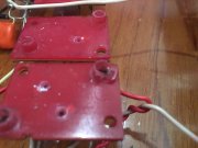
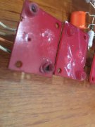
This is what I found, do you think this potential short circuit of the collectors would have caused the issue? These transistor pads are for Q11R and Q11L, the driver transistors.
Cup 1.jpg
Cup 2.jpg

Mark
 

Gepetto

Administrator
Staff member
Joined
May 15, 2011
Messages
13,553
Location
Sterling, MA
Tagline
Old 'Arn Enthusiast
That one socket looks pretty roached Mark. PL used those cheap Keystone sockets that easily break and crush, should have gone more upscale than those. Most of the back walls I have removed have had one or more broken barrels.
 

mlucitt

Veteran and General Yakker
Joined
Jun 24, 2011
Messages
3,375
Location
Jacksonville, FL
Been away for awhile tending to minor situations along the line of "Life is what happens to you while you're making other plans."
Anyway, the 'Mule' is slowly getting put back together. The troublesome backplane point-to-point wiring has been replaced with Joe's new Backplane boards and a power-on test showed good results with some interesting observations.

1. With just the Backplane boards installed and the PL400 powered up (no control board, no output transistors) the DCP relay drops out after 1-2 minutes. Checking the voltage on the L and R outputs on the DCP terminals, there was some DC voltage (about 1-1.5 VDC), more on the left channel. The relay was doing it's job, opening when DC is detected but why was there slowly increasing DC voltage on the speaker outputs with no output transistors or control board? Also, I am checking with a digital Fluke meter, so it might be DC voltage with .001 mA of current.

2. When power is removed from the amp, I like to watch the bulk capacitors slowly lose charge. The negative side stayed at -85.5 VDC for almost 10 minutes and then slowly started to decrease, an hour later it was still -75 VDC. The positive side stated dropping right away and was down to +49 VDC after 10 minutes and at an hour was under +25 VDC. Shouldn't they be roughly the same?

Thoughts?
 

oldphaser

Chief Journeyman
Joined
Sep 8, 2012
Messages
845
That one socket looks pretty roached Mark. PL used those cheap Keystone sockets that easily break and crush, should have gone more upscale than those. Most of the back walls I have removed have had one or more broken barrels.
Joe,

Regarding TO-3 style sockets which were used in Phase Linear 400's and 700 series amplifiers:

The first generation of sockets Phase Linear had square corners were made by (United International Dynamics Corp) UID Electronics division of AMF (UID part number PTS-10E).
UID had a number of locations during their history that I am aware of:

Boston, MA

243 Lexinton
Waltham, MA

2029 Taft St.
Hollywood, FL

4105 Pembroke Rd
Hollywood, FL 33021

and

777 Westchester Ave.
White Plains, N.Y.

According to the USPTO listing utilizing the UID logo (that you see used on the transistor sockets and slide-switches): The first use in commerce was November 1967. The filing date was April 24, 1968. The registration date was July 8, 1969. The "Live/Dead Indicator": shows this as "DEAD". NOTE: UID was in business a number of years previous to 1967.

William Gluck was a chief engineer and "mgr electrical componets".

Larry N. McLenagan was president of UID for 8 years.

NOTE: UID Electronics also made "normal/direct coupled" switches used on 700B and 700 series two amplifiers.
https://worldwide.espacenet.com/pub...T=D&ND=3&date=19720704&DB=EPODOC&locale=en_EP


The second generation of sockets Phase Linear used had round corners and were made by Electronic Essentials Inc (EEI) (EEI part number 1004-5A)
EEI was located in Woodside NY 55982 and then 60-20 34th Ave Woodside, NY 11377-2212
According to an old USPTO (US Patent and Trademark Office listing) their products were first used in commerce Feb 14, 1971. The filing date Nov 8, 1978. The registration date was June 24, 1980. The "Live/Dead Indicator": shows this as "DEAD". The cancellation date was Nov 21, 1986.

The Keystone part number is 4618. All of the ones I have purchased from them have had the EEI logo on them. My guess is that Keystone either bought the remaining inventory or the equipment to fabricate them.

All of the sockets noted above were designed with a thread for a #6-20 screw. If my memory serves me correct, Dean told me that the torque spec was something like 7 in. lbs. but the employees were told to torque to 12 in. lbs. This caused many of the sockets hole diameters to enlarge when over-torqued. When they became enlarged they would use a #7 screw. NOTE: I also doubt that the employees used any torque screwdrivers. More than likely they were using their "acquired feel".

When I first met Dean and was repairing amplifiers he use to double-check all my torque on the TO-3 socket screws. Eventually he was pleased with my "acquired feel" and stopped checking. Perhaps I should acquire a dial torque wrench so I can measure the break-away torque (as measured CCW) after torquing some screws both by hand and using a torque screwdriver (set to 7 and 12 in lbs). Then I should be able to correlate the results.

A #6-20 screw has a major diameter (as measured over the crest of the threads) with a min of approx .135" and a max of .139" (nominal .138")
A #7 screw has a major diameter nominal dimension of .151". This becomes an issue as the I.D. of the boss (a.k.a barrel) (I recently checked on a new Keystone 4618) is approximately .140".

There are many cases of amplifiers that were built whereby Phase Linear used #7 screws exclusively. In those cases, many of the barrels are broken. In which case the build is good for only one use at best because when you go to repair the amp the socket will more than likely need to be replaced.

Unfortunately, some of the employees at Phase Linear were not very careful in ensuring that the socket "boss" got seated properly into the heat-sinks which caused some to be squashed. This squashing could have been eliminated by using one hand on the socket inside the chassis (ensuring proper alignment) and the other hand while torquing the screw. Usually I do this by first aligning and tightening the top and bottom sockets in the vertical bank of sockets.

When I repair a Phase Linear amplifier, I remove all the heat-sinks. This allows me to lift up the output stage and inspect several things which include the emitter resistors for bulges and cracks as well as the transistors sockets for breaks, cracks or a squashed "boss".

After examining the sockets, I also reform the contacts and clean and lubricate them. Subsequently I have had no further issues.

My favorite screws Phase Linear used were the #6 slotted screws used on early 400 and 700 series 1 amplifiers. For some reason they didn't create the same issues as the hex head screws did.


Ed
 
Last edited:

Gepetto

Administrator
Staff member
Joined
May 15, 2011
Messages
13,553
Location
Sterling, MA
Tagline
Old 'Arn Enthusiast
Been away for awhile tending to minor situations along the line of "Life is what happens to you while you're making other plans."
Anyway, the 'Mule' is slowly getting put back together. The troublesome backplane point-to-point wiring has been replaced with Joe's new Backplane boards and a power-on test showed good results with some interesting observations.

1. With just the Backplane boards installed and the PL400 powered up (no control board, no output transistors) the DCP relay drops out after 1-2 minutes. Checking the voltage on the L and R outputs on the DCP terminals, there was some DC voltage (about 1-1.5 VDC), more on the left channel. The relay was doing it's job, opening when DC is detected but why was there slowly increasing DC voltage on the speaker outputs with no output transistors or control board? Also, I am checking with a digital Fluke meter, so it might be DC voltage with .001 mA of current.

2. When power is removed from the amp, I like to watch the bulk capacitors slowly lose charge. The negative side stayed at -85.5 VDC for almost 10 minutes and then slowly started to decrease, an hour later it was still -75 VDC. The positive side stated dropping right away and was down to +49 VDC after 10 minutes and at an hour was under +25 VDC. Shouldn't they be roughly the same?

Thoughts?
Does the bulk cap decay behave similarly when you remove the rail fuses from the fuseholders?
 

mlucitt

Veteran and General Yakker
Joined
Jun 24, 2011
Messages
3,375
Location
Jacksonville, FL
Does the bulk cap decay behave similarly when you remove the rail fuses from the fuseholders?
I will try that now, didn't think to remove any unseen load. The negative side will probably not change, because that decay was slow. The positive side may change, and could point to a leaky cap on one of the Backplane Boards, no?
 

Gepetto

Administrator
Staff member
Joined
May 15, 2011
Messages
13,553
Location
Sterling, MA
Tagline
Old 'Arn Enthusiast
I will try that now, didn't think to remove any unseen load. The negative side will probably not change, because that decay was slow. The positive side may change, and could point to a leaky cap on one of the Backplane Boards, no?
We'll see where the debugging takes us...
 

mlucitt

Veteran and General Yakker
Joined
Jun 24, 2011
Messages
3,375
Location
Jacksonville, FL
I powered up the amp and pulled out the rail fuses. Then I removed AC power. After five minutes of decay, the following voltages were measured referenced to the Star Ground:
Fused B+ was +.092 V
Fused B- was -59 V and dropping slowly
Seems like the negative rail voltage is "holding" after power is removed with no load and no known connection to the bulk capacitors. After an hour this voltage was -30 V and still dropping slowly. I drained the negative bulk cap with a 200 Ohm resistor and the Fused B- was still -28 V and dropping slowly. Is this normal?
The positive rail voltage is dropping across some resistance. This could be the DCP, and I could disconnect the positive rail voltage to the DCP to check this.

Unfused B+ was +79 V
Unfused B- was -83 V

The bulk capacitors are holding voltage almost equally with the rail fuses pulled, after an hour the voltages were +72 V and -80 V. No issue there.
 

Gepetto

Administrator
Staff member
Joined
May 15, 2011
Messages
13,553
Location
Sterling, MA
Tagline
Old 'Arn Enthusiast
I powered up the amp and pulled out the rail fuses. Then I removed AC power. After five minutes of decay, the following voltages were measured referenced to the Star Ground:
Fused B+ was +.092 V
Fused B- was -59 V and dropping slowly
Seems like the negative rail voltage is "holding" after power is removed with no load and no known connection to the bulk capacitors. After an hour this voltage was -30 V and still dropping slowly. I drained the negative bulk cap with a 200 Ohm resistor and the Fused B- was still -28 V and dropping slowly. Is this normal?
The positive rail voltage is dropping across some resistance. This could be the DCP, and I could disconnect the positive rail voltage to the DCP to check this.

Unfused B+ was +79 V
Unfused B- was -83 V

The bulk capacitors are holding voltage almost equally with the rail fuses pulled, after an hour the voltages were +72 V and -80 V. No issue there.
Yes disconnect the DCP, it is powered off the positive rail only
 
Top