mlucitt
Veteran and General Yakker
Good to know. And I keep my wire runs as short as possible. It is amazing how much wire I pull out of a PL700B.A short run of wire has pretty amazing inductance.

Good to know. And I keep my wire runs as short as possible. It is amazing how much wire I pull out of a PL700B.A short run of wire has pretty amazing inductance.
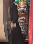
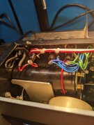
yes sir, mr. george of the jungle!!!!While I have this apart again, I going to replace a black bias wire that goes between the back planes and control board. Knicked it when I stripped it and this is the result. All the wires that go to the Phoenix connectors need tinned after stripping. Watch for knicked strands.
mine will look that nice....just wait and see....The bias transistor wiring with 6 good wires.
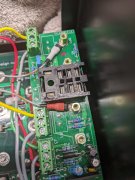
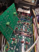
pic??Not happy with the clearance between the meter stud and copper bus bar. Let the control board pivot out on it's wiring, and the storage cap screws are pretty much a straight shot. Loosen the screws, rotate the caps, lowering the bus bar.
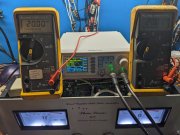
Hi GeorgeChecking meter calibration.
Here's how on the 400 S1.
Connect your signal generator to the RCA inputs.
Connect your VAC meter to the speaker jacks.
Input a 500 Hz sine wave starting at 1 VAC amplitude. Slowly raise the amplitude, stop when the VAC meter shows 20 VRMS.
The VU meters needles should be close to the "100" on the VU meter. This "100" means 100 watts output.
These meters are not very accurate or highly responsive to output levels.
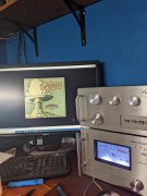
One reason some of us prefer the WOAD Cylon meters, in the Series 2 style amps.
These meters never move or swing in the small room system I use it in.
Tomorrow, I'll put this in the big system driving the JBLs and stress test it. Will get her as warm as she has ever gotten and take her temperature at the transformer, vents, and heatsinks.