
You are using an out of date browser. It may not display this or other websites correctly.
You should upgrade or use an alternative browser.
You should upgrade or use an alternative browser.
First PL700 Check Out
- Thread starter Kma4444
- Start date


Alright so here's something unusual for me so far. This one passed the checks and makes pleasing sounds. Pretty neat, it actually made it into the rack! Not sure if I should use it but it does seem to work. Kind of rough looking and it's lights are kind of a singular thing. It's cool to see a needle move to music anyway. 


- Joined
- Jan 14, 2011
- Messages
- 75,903
- Location
- Gillette, Wyo.
- Tagline
- Halfbiass...Electron Herder and Backass Woof
Always check fuses first. Sounds like a rail fuse is blown..
wattsabundant
Chief Journeyman
On 400's both channels use the same fuses so if a fuse blows both channels will be bad. I'm guessing an oscilloscope is out of the question. A scope instantly points to the general area of trouble. In lieu of a scope, check all of the transistors and diodes in the bad channel per the manual. Test the transistors using the diode function on the meter and compare questionable readings with as good channel.
If you've got one junker amp, pull parts form it to fix the others
It looks like you're using a welding table as a bench. I'd suggest some kind of insulator such as a piece of thin carpet. Ff the board flops down and hits the bench, and there is voltage on the main caps, that could be trouble.
As for the pic of the rack, I'll never tell a man he has a nice rack.
I do have an oscilloscope that I also got from my dad but no leads for it and I haven't done much besides power it up.
I was talking yesterday with my help in the shop saying I really should put a non-conductive cover on the bench, thanks for the additional and needed prodding on that.
Ha ha ha, I appreciate the reserve on referring to one's rack in the positive. Let's leave it at it's been noticed and move on!!!!!!
Quick update, I now have a functioning oscilloscope. I put the 700b #3 up on the now electrically insulated bench and replaced the one bad transistor with a new one. Fuses are good and it passes the DBT. Left channel shows almost 0 volts DC and right has .035. I am not sure what I should check from here on. I know there is a bias to be set and I see and have read how to do it but I could use maybe a pointer or two. I am willing to test or check whatever as I want to learn the right way to do things.
Thanks all again.
Thanks all again.
wattsabundant
Chief Journeyman
I use BNC-binding post connectors on my scope and cables with dual bananna jacks. Download a signal generator on your phone. Inject a sine wave from the signal generator into the amp and look at it with the scope. Verify the level is nearly the same at 20HZ, 1khz and 20Khz. If the level drops starting around 100 HZ, first verify the signal generator level is not changing, then look at C6. If the sine wave is not symmetrical see the troubleshooting section in the manual. Bias procedure is covered in the manual.
Consider buying a couple load resistors. Parts Express load resistor. at only 100 watts they'll get hot quick but will work for short term testing.

Consider buying a couple load resistors. Parts Express load resistor. at only 100 watts they'll get hot quick but will work for short term testing.
Last edited:
- Joined
- Jan 14, 2011
- Messages
- 75,903
- Location
- Gillette, Wyo.
- Tagline
- Halfbiass...Electron Herder and Backass Woof
And if you change C6, replace it with a 470uf/25 volt audio cap such as Nichicon Muse or Fine Gold. Improves low frequency response..
That's great info, thank you so very much. As it happens I do have a BNC binding post connector exactly like you pictured there, good news. I will do as you suggest.
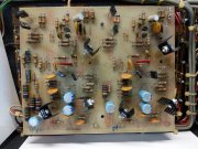
When doing the bias test it looks to me like the resistors I am looking for are coming off the driver transistors, the bottom ones?
Thank You again
When doing the bias test it looks to me like the resistors I am looking for are coming off the driver transistors, the bottom ones?
Thank You again
wattsabundant
Chief Journeyman
No, theyre on the outputs. Color is brown-black-black.When doing the bias test it looks to me like the resistors I am looking for are coming off the driver transistors, the bottom ones?
Thank You again
OK, I found the correct resistors I'm pretty sure. They are 3rd down on the left side of the two rows of transistors and 4th down on the right row. The left channel comes in about .371 and the adjuster works to change the value. The right side shows no voltage at all. I do have -88 volts on the right side of the right rail for the right channel, if I am making sense. I will keep poking around checking for voltage using the diagram.
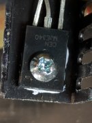
So the only thing I have been able to find, with any confidence, is that the voltages in and out of q10 on either side are quite different. The left lines up reasonably well with the values on the diagram but the right shows about .5 volt on the center pin, the one that goes to the red wire on the board and the right pin has just a couple thousandths of a volt.
mlucitt
Veteran and General Yakker
That looks like a non-standard transistor. Can you give us a picture with a little wider field of view?
You are moving in the right direction...
You are moving in the right direction...
mlucitt
Veteran and General Yakker
And they liked those TO-126 transistor packages. With the heat sinks upside down...
WOPL Sniffer
Veteran and General Yakker
And they liked those TO-126 transistor packages. With the heat sinks upside down...
I see nothing upside down
I am going to order a couple of the transistors like I took a picture of. Unless someone thinks it's not a good choice for that application. Hopefully that will get me a step closer on this one. I'm really looking forward to things getting rolling again so I can order a pile of WO stuff and get one of these truly operational.
Thanks All
Thanks All
- Joined
- Jan 14, 2011
- Messages
- 75,903
- Location
- Gillette, Wyo.
- Tagline
- Halfbiass...Electron Herder and Backass Woof
First, do you know it's bad?. How did it check in circuit? If it was questionable , did you test it out of circuit?
Q8, L&R, Q9, L&R are NOT 2N1304's and 2N1305's. Those are the protection circuit transistors. They are also germanium. There are silicon transistors in their place, near as I can tell.
Q10 should be a 2N3439....
Q8, L&R, Q9, L&R are NOT 2N1304's and 2N1305's. Those are the protection circuit transistors. They are also germanium. There are silicon transistors in their place, near as I can tell.
Q10 should be a 2N3439....
wattsabundant
Chief Journeyman
Having worked in the power electronics business for more than 40 years there is one thing that has become readily apparent. I've learned that manufacturers know noting about their product. The longer they are in business, the less they know. Consequently, a person should never read the service manual for a product. Phase Linear is a perfect example. Section 6 of the 700B manual is loaded with misinformation on how to test transistors.
The patent that was awarded for the protection circuit used germanium transistors. Nobody at Phase Linear knew that germanium transistors had a .3 volt base/emitter drop versus .6 volts for silicon. So the prudent thing to do is change out the germaniums for silicon and it will work fine. And you don't need to test it because anybody would know it will work. As for the TO5 transistors in the final voltage stage and predrivers, you can replace them with any old transistor lying around and a distortion analyzer isn't needed to verify that it doesn't oscillate at a megahertz and melt tweeters. Replace the TO92's in the front end with anything and the offset and the noise floor will drop dramatically. That little bias transistor mounted on the heatsink can be replaced with anything. Save yourself the hassle of mounting it on the heatsink and mount it on the board. The bias will be more stable than ever.
Referring once again to the troubleshooting section of the 700B manual, do not test the transistors in circuit using the procedures. It's far better to replace every transistor and diode on the board. You can buy a kit on EBAY. Even if the new ones are installed backwards the amp will still work fine. Heaven forbid it doesn't work, change out everything again. Certainly it will work then. Above all else, never compare readings of a known good channel with that of a defective channel. Any readings taken should be done with the power turned on as it is the safest thing to do.