Carver C-500 - valid candidate for White Oak Audio upgrade???

grapplesaw

Veteran and General Yakker
Joined
Aug 13, 2014
Messages
2,765
Location
Vancouver
Tagline
---
#21
OK, I purchased and installed the output protection relay board and after firing it up I had some hum on the right channel. :(. So in the process of trying to track down the source, I managed to touch something that bricked it. (DC at output) Well, not really, because I painstakingly went through all of the components and circuits trying to find a bad component, and everything looked fine. Grrr. Then I decided that I needed to figure out how the thing is supposed to work so that I could track the voltages through the driver board. (driver board had to be the culprit) I took a photo of the trace layout, flipped it and overlayed with the component layout photo. I brought those into Visio and added components and traces. You know how much a PITA it is to reverse engineer even a fairly simple circuit? Well this circuit is not all that simple... Anyway I then got a copy of LTSpice and entered the circuit from the service manual (there are two versions in the manual), then compared the actual circuit from the unit to the spice drawing. Not the same. A third version! They are all fairly similar but there are some differences mainly at the signal input and somewhat different resistor values in various places. I wanted to try to get the DC bias analysis from the spice model to figure out why I had DC at the output. I never really got that to work, partly I think because the amp uses a transient at startup to bootstrap the driver into an "on" state. That is what I think, anyway.

Result. I gave up on the spice model but I learned a lot about the circuit in the process. Carver inverts the signal to the right channel at the input. There is an op-amp at the input to each channel (LF356) and in the manual he drives the left side into the non-inverting input and the right side into the inverting input. On my amp, it is different. He drives both on the non-inverting input. He then added another op amp with unity gain to the right channel to invert the input phase. This turned out to be the problem as that op amp must have gotten fried and was putting out about 2V DC with zero volts input. What I did for now was just to hook the right input directly to the non-inverted input op-amp and bypass the extra op-amp. That seemed to set everything straight.

My question then is... Why did Carver invert the right channel phase? I mean he makes a big deal of it in the output connectors and in the service manual, but is it really necessary? Is this a trick to even out the power draw in the amp reducing distortion?

Oh, and I now have driver board layouts and circuit schematics. I still have no idea how the protection circuits are supposed to work, and I don't really understand the signal flow from input to output of the driver board.

Anyway, the beast works, and I'll probably order an RC4136N quad op-amp if they still make them. It's funny that he had used this extra quad op amp on the right side but only used one section and shorted the other three.

Sterling
Sterling I am glad you have it running. The carversite has the manual with schematic drawings if you go ther you can down load them. http://thecarversite.com/manuals/mandir/Carver C-500 service manual.pdf

To to try to answer your question on why the one inverted channel it is done to give the ability to make a bridged mono output from both channels. The two channels are in fact out of phase. The wiring on the stock binding posts reversed the pos and neg of one channel so it would deliver in phase out put. By bridging the two outputs the mono channel is created by using the two hot legs of each channel to the speakers. When in bridged mode the amp sees a load equal to 1/2 the connected speaker load. so if you have 8 ohm speaker the amp sees a 4 ohm load. This also more than doubles the output power and cuts the damaging factor in half. This bridged setup is useful to drive a sub or in a multi amp system.

inverting the op amp on one channel is done by having the dual op setup on that one channel. Installing a Whiteoak pl14-20 board you loose this ability, how offen does one need to bridge an amp other than Perry and Me that is.

If if you added Don's protection board as I did then you must check the path of each pos an neg input to the board from the backplane. This should reverse the binding posts from stock on one channel. Check if the binding posts are now out out of phase. With the DCP board in is imparitive that the ground and hot go through the board correctly. If you have done this correctly the binding posts will now be out of phase and this can be easily corrected by revering the positive and negative on one speaker cable. Bob jockeyed the wiring in the original to make it simple to get back in phase at the outputs.

The last thing is the protection circuit is kind of smoke and mirrors combined with some function. This circuit is a derivative of the Pl32 board used in the d-500 phase linear. It reduces the input signal to the opamp on both channels to a point where the variance dectected is reduced back to normal range though lowering output
with the added DCP board you have increased the safety margin to the point where I think the on board cuircuit is redundant and can be eliminated if you choose.


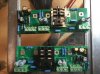
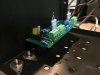
Here are photos of the DCP board setup on a stock c-500 output. The board I built for my c500 is built inverted compaired to the phase 400. The c500 is shown in the top half of the two assembly pictured and the phase 400 in the lower half. This was necessary due to the outputs and inputs location being inverted on the chassis between the c500 compared to the phase 400
 

Attachments

Last edited:

savaden

New Around These Parts
Joined
Jan 5, 2017
Messages
5
Tagline
---
#22
Thanks for the explanation. I did think about that after I posted the question, so I suppose that is the whole reason. (bridging). There are two versions of the driver board schematic in the service manual, an early and later one. Also the board layout for the early version shows hand Xed out components and jumpers. None of those match the component layout of the actual board or "engineering changes". Ha. I did install the output relay board just as you did, and it works fine. I did use a shielded cable to run the AC from the bridge rectifier over to the board. Overkill, perhaps. I also rearranged the output wires and did some other cleanup of wire routing.
Carver C-500.gif

SV
 

grapplesaw

Veteran and General Yakker
Joined
Aug 13, 2014
Messages
2,765
Location
Vancouver
Tagline
---
#24
I'm at a loss, can somebody tell me what "vertaclly bi-amped" means???
That's when you stack two amps with one on top of the other and run the bass with one and the mid/ highs with the other and then try to tell all about it here on the forum using your phone to type without spell check turned on.

But of coarse you need to have a working phone Perry

I am sorry for your loss
 
Last edited:

WOPL Sniffer

Veteran and General Yakker
Joined
Aug 10, 2015
Messages
11,226
Location
Minnie-Soda
Tagline
Screw it
#25
That's when you stack two amps with one on top of the other and run the bass with one and the mid/ highs with the other and then try to tell all about it here on the forum using your phone to type without spell check turned on.

But of coarse you need to have a working phone Perry

I am sorry for your loss
Thats some funny shit there Glen.........
I thought I was learning some new fancy processes or procedures..... damn, all i need is a brokedick phone? Hell, got that cuvered...
 

rfitts46

New Around These Parts
Joined
Jan 9, 2017
Messages
1
Tagline
---
#26
installed one of Don's DC protect board in PL400. want to install Don's board in C-500 but the phase inverted channel is throwing me a loop.

I get stuffing the board as a mirror image. if you do that do the binding posts line up to the pcb thru holes?

are there wiring considerations different than the wiring connections if you were connecting it to a PL400? due to the phase inverted channel?
 

grapplesaw

Veteran and General Yakker
Joined
Aug 13, 2014
Messages
2,765
Location
Vancouver
Tagline
---
#27
So it’s not that complicated and yet it is.
the carver c-500 has one inverted channel so you can bridge the two hot outputs and make a 500 watt mono channel. Carver in his wisdom changed one channel hot binding post to ground within the the chassis to hide the fact you are using the two hot legs.
So what you have to do is connect the binding posts as per Dons board out puts and forget the bridge markings on the outside of chassis. If you want to bridge it just go to the two hots and do not connect to either ground. You actually don’t have to do anything except hock it up 38A73066-1DE2-4EBB-8133-6B746AE31C8E.jpeg
 

grapplesaw

Veteran and General Yakker
Joined
Aug 13, 2014
Messages
2,765
Location
Vancouver
Tagline
---
#30
Update. Whatch out how you invert the ic chip when you put it together as the Pin out must be maintained.

also it probably gives about 800 watts into 8 ohms bridged mono. Then you blow the mains fuse. No 4 ohm loads in bridged mono please.

As driver cost are skyrocketing I am not testing below 7 ohms in bridged configuration. Having 10 mj21195/96 drivers per channel I wonder if that may let it go to 4ohm load but I will not be the one finding out.
 

wattsabundant

Chief Journeyman
Joined
Apr 26, 2011
Messages
846
Location
Central Ohio
#31
...Having 10 mj21195/96 drivers per channel I wonder if that may let it go to 4ohm load but I will not be the one finding out.
. This is essentially a 400 series II. To clarify, each channel has 2 drivers and 8 outputs. The 400II had 6 outputs. Do the current sharing test and if all is good I wouldn't hesitate to put in 10 amp fuses and test it, short term into 4 ohm bridged load. The loadbank may not like it.
 

grapplesaw

Veteran and General Yakker
Joined
Aug 13, 2014
Messages
2,765
Location
Vancouver
Tagline
---
#32
Hi Don
Yes that is the configuration having one additional output that the PL400
I have two units and have done two others c-500’s with Joe’s control boards in a full complementary setup. I put sets of mj15024/25 in both of mine which came out of some 700’s I upgraded. This configuration dose not allow bridged setup so I feel good about using the mj15024/25’s in this setup

I am curious of your view on transformer saturation When using a PL 400 with 10 amp main fuses. I built a couple of inverted channel 400’s that will put out 700 wats in 8 ohms as a mono bridged set up before the main input fuse blow. Many suggested bigger main fuses but I worried about cooking the transformer. I do not know what to look out for when driving a transformer into the terminal range. Any info or suggestions would be great

take care
Glen
 

Gepetto

Administrator
Staff member
Joined
May 15, 2011
Messages
13,530
Location
Sterling, MA
Tagline
Old 'Arn Enthusiast
#33
Hi Don
Yes that is the configuration having one additional output that the PL400
I have two units and have done two others c-500’s with Joe’s control boards in a full complementary setup. I put sets of mj15024/25 in both of mine which came out of some 700’s I upgraded. This configuration dose not allow bridged setup so I feel good about using the mj15024/25’s in this setup

I am curious of your view on transformer saturation When using a PL 400 with 10 amp main fuses. I built a couple of inverted channel 400’s that will put out 700 wats in 8 ohms as a mono bridged set up before the main input fuse blow. Many suggested bigger main fuses but I worried about cooking the transformer. I do not know what to look out for when driving a transformer into the terminal range. Any info or suggestions would be great

take care
Glen
Hey Glen
Transformer saturation will not occur because you load it excessively, its losses will just go up more. Saturation occurs when you do not have enough core area to support the input voltage level at a given frequency. This usually is seen with 50Hz operation at high input line voltage. Since these transformers were designed to support 50/60 Hz, you are well away from any saturation while running on 60 Hz AC mains.
 

grapplesaw

Veteran and General Yakker
Joined
Aug 13, 2014
Messages
2,765
Location
Vancouver
Tagline
---
#34
Hey Glen
Transformer saturation will not occur because you load it excessively, its losses will just go up more. Saturation occurs when you do not have enough core area to support the input voltage level at a given frequency. This usually is seen with 50Hz operation at high input line voltage. Since these transformers were designed to support 50/60 Hz, you are well away from any saturation while running on 60 Hz AC mains.
Ok Joe thanks for this.
 
Top