
P.L.F.
Journeyman
- Joined
- Sep 9, 2012
- Messages
- 419
- Location
- Poland, Warsaw (Central Europe)
- Tagline
- I love BIG amplifiers!
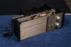
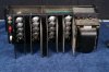
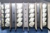
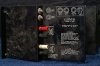
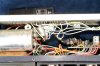
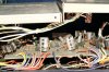
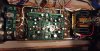
From time to time one can find Carver C-500 amps on sale (here is a fine example of the amp -> https://youtu.be/LdySAN72XSM). It looks similar to a PL400II, but with more power at least on specs. There is also extra output transistor per bank (4 instead of 3), so more like PL700II backplane dimensions? The C-500 driver board is however visibly different from PL-36.
Apparently VAS works hotter vs PL400II. Higher voltage was implemented to expand bandwidth and increase slew rate. The PCB had as well DC in / speakers out protection circuit built in. The other key different feature in compare to PL400II was the fact that Carver C-500 was ‘internally phase-inverted’ in one channel allowing bridged operation, so you could run it mono (500W) just by using the two red / white posts, provided speakers’ impedance was watched and cooling present. Power outputs were normally marked as C1000 - not sure what they really are. On the pics attached, there are MJ15011, quasi topology. That gear could have been repaired.
The amp looks like WOPL upgrade ready. Does anybody have this model to check dimensions and spacing requirements? All in all it could be an additional power amplifier with WOA upgrade available, well maybe without the bridging option…
Your views?
Attachments

Last edited:


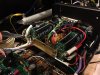
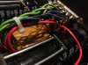
") Recapped one, didn't bother with the other one. They both work the same.
Recapped one, didn't bother with the other one. They both work the same.  . So in the process of trying to track down the source, I managed to touch something that bricked it. (DC at output) Well, not really, because I painstakingly went through all of the components and circuits trying to find a bad component, and everything looked fine. Grrr. Then I decided that I needed to figure out how the thing is supposed to work so that I could track the voltages through the driver board. (driver board had to be the culprit) I took a photo of the trace layout, flipped it and overlayed with the component layout photo. I brought those into Visio and added components and traces. You know how much a PITA it is to reverse engineer even a fairly simple circuit? Well this circuit is not all that simple... Anyway I then got a copy of LTSpice and entered the circuit from the service manual (there are two versions in the manual), then compared the actual circuit from the unit to the spice drawing. Not the same. A third version! They are all fairly similar but there are some differences mainly at the signal input and somewhat different resistor values in various places. I wanted to try to get the DC bias analysis from the spice model to figure out why I had DC at the output. I never really got that to work, partly I think because the amp uses a transient at startup to bootstrap the driver into an "on" state. That is what I think, anyway.