Carver C-500 - valid candidate for White Oak Audio upgrade???

P.L.F.

Journeyman
Joined
Sep 9, 2012
Messages
419
Location
Poland, Warsaw (Central Europe)
Tagline
I love BIG amplifiers!
#1
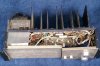
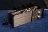
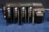
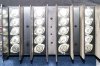
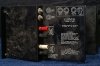
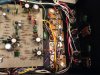
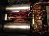
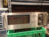
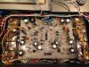
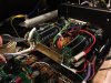
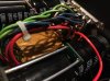
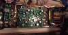
From time to time one can find Carver C-500 amps on sale (here is a fine example of the amp -> https://youtu.be/LdySAN72XSM). It looks similar to a PL400II, but with more power at least on specs. There is also extra output transistor per bank (4 instead of 3), so more like PL700II backplane dimensions? The C-500 driver board is however visibly different from PL-36.

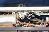
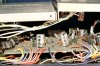
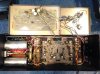
Apparently VAS works hotter vs PL400II. Higher voltage was implemented to expand bandwidth and increase slew rate. The PCB had as well DC in / speakers out protection circuit built in. The other key different feature in compare to PL400II was the fact that Carver C-500 was ‘internally phase-inverted’ in one channel allowing bridged operation, so you could run it mono (500W) just by using the two red / white posts, provided speakers’ impedance was watched and cooling present. Power outputs were normally marked as C1000 - not sure what they really are. On the pics attached, there are MJ15011, quasi topology. That gear could have been repaired.

The amp looks like WOPL upgrade ready. Does anybody have this model to check dimensions and spacing requirements? All in all it could be an additional power amplifier with WOA upgrade available, well maybe without the bridging option…

Your views?
 

Attachments

Last edited:

laatsch55

Administrator,
Staff member
Joined
Jan 14, 2011
Messages
74,224
Location
Gillette, Wyo.
Tagline
Halfbiass...Electron Herder and Backass Woof
#2
I think the question to begin with is "How many were sold"?? And go from there. The chassis are completely different, so anything but the driver board would be "ground up" development.
 

Northwinds

Veteran and General Yakker
Joined
Mar 18, 2013
Messages
7,546
Location
Coventry, CT
Tagline
Fondler errrr... fan of all Nav's avatars
#3
They do look remarkably similar. The cylon eyes are cool how they react in the vid!
 

P.L.F.

Journeyman
Joined
Sep 9, 2012
Messages
419
Location
Poland, Warsaw (Central Europe)
Tagline
I love BIG amplifiers!
#4
I think the question to begin with is "How many were sold"?? And go from there. The chassis are completely different, so anything but the driver board would be "ground up" development.
Yes Lee, you are right. It is like a PL400 chassis with extra row for outputs. A different story... Pity..
 

gadget73

Journeyman
Joined
Aug 29, 2014
Messages
465
Tagline
---
#6
You can definitely see the similarity to a PL 700-II though. Looks like the inside chassis are is shrunken to the point where it would be obnoxious to work on.
 

savaden

New Around These Parts
Joined
Jan 5, 2017
Messages
5
Tagline
---
#7
More on the C-500 (moron?)

This is my first post, so be kind... Anyway, I picked up a C-500 at the local thrift, and it appears not to have been messed with. Hooked it up and verified working properly. Until it let all the steam out of one of the power supply caps. Sounded just like my espresso machine blowing the pressure relief valve. Easy to disassemble and I think the WOA capacitor upgrade would fit right in there, or if I could find a new home for the diode bridge, 2" diameter caps would seem to fit. From the descriptions I have read this does not need the output protection relay upgrade? Not sure. Also not sure if the driver board is the same as the PL400. Pics attached. Not really in order, but you get the idea.
IMG_8780.jpg IMG_8784.jpg IMG_8783.jpg IMG_8779.jpg IMG_8781.jpg

Sterling Vaden
Black Mountain, NC
 

WOPL Sniffer

Veteran and General Yakker
Joined
Aug 10, 2015
Messages
11,227
Location
Minnie-Soda
Tagline
Screw it
#8
The 15,000uf 160V caps are pretty big, don't know if they'll fit or not. Here is the measurments:

Length 4.5" Dia 2.5" Circum. 8"


grapplesaw

Veteran and General Yakker
Joined
Aug 13, 2014
Messages
2,765
Location
Vancouver
Tagline
---
#11
This is my first post, so be kind... Anyway, I picked up a C-500 at the local thrift, and it appears not to have been messed with. Hooked it up and verified working properly. Until it let all the steam out of one of the power supply caps. Sounded just like my espresso machine blowing the pressure relief valve. Easy to disassemble and I think the WOA capacitor upgrade would fit right in there, or if I could find a new home for the diode bridge, 2" diameter caps would seem to fit. From the descriptions I have read this does not need the output protection relay upgrade? Not sure. Also not sure if the driver board is the same as the PL400. Pics attached. Not really in order, but you get the idea.
View attachment 27693 View attachment 27694 View attachment 27695 View attachment 27691 View attachment 27692

Sterling Vaden
Black Mountain, NC
i just redid one. You can use the WhiteOak capacitor setup. I have a 10,000 plus 6,800 paired for each rail.
Here is some photos.
 

Attachments

grapplesaw

Veteran and General Yakker
Joined
Aug 13, 2014
Messages
2,765
Location
Vancouver
Tagline
---
#12
The carver board has protection but not for DCP on the outputs.
Here is a full conversion to Dons board with Joe's control board and full complimentary setup
 

Attachments

Last edited:

savaden

New Around These Parts
Joined
Jan 5, 2017
Messages
5
Tagline
---
#13
BTW this thing came with the original user manual attached. Ser# 0033. Where is a link to the output protection board? Is the Rev E control board a pin for pin replacement or needs some other mods. I have downloaded the service manual. In general I like to keep things original if possible, but you know sometimes that is not possible or doesn't make sense, especially when you've got all those transistors wired in parallel. Sheesh.

I have reworked two Denon PRA 1000 pre-amps now and it is fun hunting down the glitches in those things. They have parallel wired Fets in the mc phono preamp. Had to re-solder every single connection. Twice. :) Recapped one, didn't bother with the other one. They both work the same.

I don't have a distortion analyzer, though.

Sterling Vaden
Black Mountain, NC.
 

grapplesaw

Veteran and General Yakker
Joined
Aug 13, 2014
Messages
2,765
Location
Vancouver
Tagline
---
#14
BTW this thing came with the original user manual attached. Ser# 0033. Where is a link to the output protection board? Is the Rev E control board a pin for pin replacement or needs some other mods. I have downloaded the service manual. In general I like to keep things original if possible, but you know sometimes that is not possible or doesn't make sense, especially when you've got all those transistors wired in parallel. Sheesh.

I have reworked two Denon PRA 1000 pre-amps now and it is fun hunting down the glitches in those things. They have parallel wired Fets in the mc phono preamp. Had to re-solder every single connection. Twice. :) Recapped one, didn't bother with the other one. They both work the same.

I don't have a distortion analyzer, though.

Sterling Vaden
Black Mountain, NC.
Hi Sterling

If you want to keep it original then just change the power caps and Bridge rectifier add the smoothing caps to the bridge and use some 10,000 100 volt 33mm OD Capacitors and you will be happy. There is no information on upgrading the amp short of my thread here

http://forums.phxaudiotape.com/show...-C-500-upgrade-to-WOPL?highlight=carver+c-500
 
Last edited:

grapplesaw

Veteran and General Yakker
Joined
Aug 13, 2014
Messages
2,765
Location
Vancouver
Tagline
---
#15
I used a Whiteoaks REv D board in my build ( sounds great) the E board is the same wiring there is a couple of wires not required from the output of each channel that the Carver board used in its protection circuit if you go WO. You can sort the rest easily using the schematic of each..

So if you want to have a great amp for 30 more years consider upgrading it you can leave it Quasi Comp or go full complimentary as I did. This amp is used every day now with my TV.


To add one of Don Imlays DCP boards you have to change the outputs. as well I had to build it with all the components on the opposite side. if you do put one in it works great just watch how you flip the IC as the bevel edge goes from inside to outside when inverted. see post 11 in this link

http://forums.phxaudiotape.com/show...-C-500-upgrade-to-WOPL?highlight=carver+c-500
 

savaden

New Around These Parts
Joined
Jan 5, 2017
Messages
5
Tagline
---
#16
Found suitable PS caps.

I think I found a couple suitable PS caps. Thanks for the 160V tip. I was looking at 100V parts. Looks like pretty close to a drop-in replacement with 20% more capacity.

http://www.tedss.com/2020063499


  • capacitance: 7,100 uf
  • voltage: 160 vdc
  • lead style: screw
  • diameter: 1.75 IN, length: 4.625 IN

Met a guy at GW today that used to work for HP at the original factory. :)

Sterling Vaden
Black Mountain, NC.
 

Funky54

New Around These Parts
Joined
Feb 24, 2017
Messages
2
Tagline
---
#17
Two C-500 vertaclly bi-amped

Great thread. Very encouraging the many WO parts work. One of mine needs some repair.
 

savaden

New Around These Parts
Joined
Jan 5, 2017
Messages
5
Tagline
---
#20
Carver C-500-033 update.

OK, I purchased and installed the output protection relay board and after firing it up I had some hum on the right channel. :(. So in the process of trying to track down the source, I managed to touch something that bricked it. (DC at output) Well, not really, because I painstakingly went through all of the components and circuits trying to find a bad component, and everything looked fine. Grrr. Then I decided that I needed to figure out how the thing is supposed to work so that I could track the voltages through the driver board. (driver board had to be the culprit) I took a photo of the trace layout, flipped it and overlayed with the component layout photo. I brought those into Visio and added components and traces. You know how much a PITA it is to reverse engineer even a fairly simple circuit? Well this circuit is not all that simple... Anyway I then got a copy of LTSpice and entered the circuit from the service manual (there are two versions in the manual), then compared the actual circuit from the unit to the spice drawing. Not the same. A third version! They are all fairly similar but there are some differences mainly at the signal input and somewhat different resistor values in various places. I wanted to try to get the DC bias analysis from the spice model to figure out why I had DC at the output. I never really got that to work, partly I think because the amp uses a transient at startup to bootstrap the driver into an "on" state. That is what I think, anyway.

Result. I gave up on the spice model but I learned a lot about the circuit in the process. Carver inverts the signal to the right channel at the input. There is an op-amp at the input to each channel (LF356) and in the manual he drives the left side into the non-inverting input and the right side into the inverting input. On my amp, it is different. He drives both on the non-inverting input. He then added another op amp with unity gain to the right channel to invert the input phase. This turned out to be the problem as that op amp must have gotten fried and was putting out about 2V DC with zero volts input. What I did for now was just to hook the right input directly to the non-inverted input op-amp and bypass the extra op-amp. That seemed to set everything straight.

My question then is... Why did Carver invert the right channel phase? I mean he makes a big deal of it in the output connectors and in the service manual, but is it really necessary? Is this a trick to even out the power draw in the amp reducing distortion?

Oh, and I now have driver board layouts and circuit schematics. I still have no idea how the protection circuits are supposed to work, and I don't really understand the signal flow from input to output of the driver board.

Anyway, the beast works, and I'll probably order an RC4136N quad op-amp if they still make them. It's funny that he had used this extra quad op amp on the right side but only used one section and shorted the other three.

Sterling
 
Top