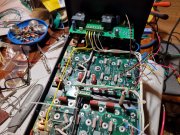
And the journey begins...

Joined
May 17, 2023
Messages
306
Location
Finland via the deep south
Tagline
Details, details
#61
What you have implemented should work, as long as the bolts are isolated (the pictures don't show under the bolt head).

I do not isolate the transformer core or cradle from chassis.

Each plate within the transformer lamination stack is isolated to help minimize eddy currents.
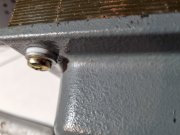
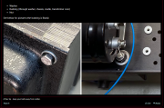
OK, I guess I went the extra mile and made sure everything was isolated. Here you can see the white bushing under the washer on the outside cap.
20231103_182551.jpg

Which is the bushing on the right side of the bolts below: As you can see all of the bushings extend into the core laminations to make sure everything is centered and isolated.
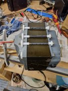
20231102_193321.jpg
 

George S.

Veteran and General Yakker
Joined
Feb 18, 2020
Messages
5,021
#62
I run the bushings under the bolt head washer and under the nut washer like Eric shows. I also add a thin nylon washer between the cradle and chassis for each bolt.
The anodizing on the chassis is a pretty good insulator as is.
The anodizing has to be broken for continuity. I figure the nylon washer doesn't hurt anything and insures a open circuit there.
Would noise be higher or lower if we removed the anodizing around the holes so the cradle had a good chassis ground?
I don't know.
 
Joined
May 17, 2023
Messages
306
Location
Finland via the deep south
Tagline
Details, details
#63
I run the bushings under the bolt head washer and under the nut washer like Eric shows. I also add a thin nylon washer between the cradle and chassis for each bolt.
The anodizing on the chassis is a pretty good insulator as is.
The anodizing has to be broken for continuity. I figure the nylon washer doesn't hurt anything and insures a open circuit there.
Would noise be higher or lower if we removed the anodizing around the holes so the cradle had a good chassis ground?
I don't know.
Well...Eric is showing the bolt head/nut bearing directly on the bushing and the washer is between the bushing and the chassis/transformer case
1699032524488.png

Electrically this works but mechanically it would be better to have the bushing sandwiched between the chassis/transformer and a washer so the loads from the bolt/nut are spread out over a larger area (and remember, I'm a mechanical engineer by schooling).

At the end of the day either approach works as it yields the desired result...electrical isolation of the bolt from the chassis and transformer core. I just went overboard by isolating everything...we'll see how it works.

Now if that friggin' alcohol would get here I could finish cleaning the boards and install them.
 

J!m

Veteran and General Yakker
Joined
Dec 24, 2019
Messages
10,705
Location
Connecticut
Tagline
BOT
#64
With soft Teflon, you for sure need to be mindful of the load distribution; however, with Nylon, the material is far more robust and should be fine in either orientation with a relatively low static load.
 
Joined
May 17, 2023
Messages
306
Location
Finland via the deep south
Tagline
Details, details
#65
With soft Teflon, you for sure need to be mindful of the load distribution; however, with Nylon, the material is far more robust and should be fine in either orientation with a relatively low static load.
Right you are...the joys of working with materials available (in a reasonable time frame)! Plus, the Teflon machines so much better than that damn Nylon.
 
Joined
May 17, 2023
Messages
306
Location
Finland via the deep south
Tagline
Details, details
#67
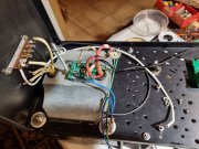
Have been doing a little AC wiring getting ready for the backplane installation and am still thinking about this "reverse polarity" light as these European plugs can go in either way. I was looking at old posts using the triac switch for hints about wiring and it hit me...you are connecting the triac into the line side of the power supply but what happens if you switch this and wire it into the neutral (as if somebody plugged in "backwards")...will it work?
20231103_232344.jpg

And yes, I think I need to go back and add a wee bit of solder to that line connection on the transformer primary :eek: Guess I was focusing on the incoming line and forgot about the transformer side...

But now I'm really curious about that Triac and if it will work if I happen to plug the amp in "backwards" o_Oo_Oo_O

Oh well, time for other thoughts...
2911246906_39cb608368.jpg
 

NavLinear

Veteran and General Yakker
Joined
Apr 12, 2012
Messages
6,056
Location
SoCal
#68
You really should open the hot lead (safety issue) so not having a polarized plug can be problematic.

BTW - I love your distracting photos. :love7:
 
Joined
May 17, 2023
Messages
306
Location
Finland via the deep south
Tagline
Details, details
#69
You really should open the hot lead (safety issue) so not having a polarized plug can be problematic.

BTW - I love your distracting photos. :love7:
I know that I should open the hot lead but my main question is will the triac even work if it is plugged in backwards. I am toying with putting in a "reverse polarity" indicator (transformer noise issue) but if the triac won't work on reverse polarity then the indicator is just that much more important...
 

mlucitt

Veteran and General Yakker
Joined
Jun 24, 2011
Messages
3,469
Location
Jacksonville, FL
#70
You are likely not going to be unplugging and plugging in your amplifier. I would suggest that you identity the "Line" or "Hot" side of your receptacle and orient your plug to provide the "Line" or "Hot" side of the AC cable to the Fuse Holder. Then your amplifier will be protected and your Triac Switch will provide a nice Turn On feature.

You may find this provides the least noise. But if not, you can always swap the Transformer Primary wires on the Terminal Strip. You should not need a Reverse Polarity Indicator.
 
Joined
May 17, 2023
Messages
306
Location
Finland via the deep south
Tagline
Details, details
#71
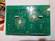
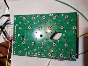
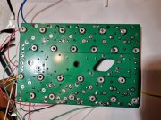
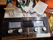
Finally got the isopropyl alcohol and cleaned the boards. Also did a little front panel assembly while I was waiting...
20231106_135211.jpg
20231106_135149.jpg
20231106_135138.jpg
20231105_225412.jpg

Any clue as to what that light film on the backplanes is and how to remove it? I'm using 99.9% alcohol so I don't think it is that. Residue from the flux?
 

MarkWComer

Veteran and General Yakker
Joined
Nov 1, 2014
Messages
3,493
Location
Gaston, SC
Tagline
Victim of the record bug since age five
#72
Evaporated alcohol leaves a trace of where it’s been. May be a teensy bit of flux mixed in with it. Shouldn’t be something to worry about.
 
Joined
May 17, 2023
Messages
306
Location
Finland via the deep south
Tagline
Details, details
#73
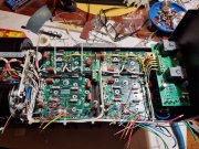
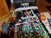
Well, it's finally starting to look like an amplifier again...got the backplanes installed and have started on the wiring.
20231106_224450.jpg
20231106_224706.jpg
20231106_224732.jpg

Next will be finishing up the fuses, get the drivers installed, check for shorts and then put some juice to it and see what she does...oh shit, I guess I need to build that DBT now :eek:

Sending out the Bat signal...


09645d13-a92b-4f11-88f0-f51b2eaeebfc.jpg
 

MarkWComer

Veteran and General Yakker
Joined
Nov 1, 2014
Messages
3,493
Location
Gaston, SC
Tagline
Victim of the record bug since age five
#75
Do you have the zoebel network on that protection circuit? Don’t need it- it’s already on the backplanes
 
Joined
May 17, 2023
Messages
306
Location
Finland via the deep south
Tagline
Details, details
#77
Don’t forget to take the Zobel RC components off the DCP board.

Love that Bat signal…
And what praytell are these "Zobel RC components"? I saw the note in the "Assembly notes for PL700 Backplane..." but didn't know what in the hell Joe was talking about. Do you have specific instructions as to what I need to remove?
 
Joined
May 17, 2023
Messages
306
Location
Finland via the deep south
Tagline
Details, details
#79
Sorry, I’m traveling this week and trying to help using my phone.

Remove the R & C components circled below.

Perfect...I was reading where the Zobel was the R/C network but didn't have a schematic for the board. Was thinking that this resistor must be the one because of the size but wasn't sure, also not positive which cap to take. Thanks and those guys will be "gone in 60 seconds".
 

WOPL Sniffer

Veteran and General Yakker
Joined
Aug 10, 2015
Messages
11,522
Location
Minnie-Soda
Tagline
Screw it
#80
Mine seem to make contact a little sooner and if you tried you might get bit but nevertheless I'm reworking the lines to power up the tip as you recommended. I like your little loop in the connecting wire, not sure mine is going to look as neat but we'll see how they turn out.

Most are smart enough to unplug the amp when dickin with it................... :)
 
Top