You are using an out of date browser. It may not display this or other websites correctly.
You should upgrade or use an alternative browser.
You should upgrade or use an alternative browser.
And the journey begins...
- Thread starter Pulpmillguy
- Start date
Robbie,Also, consider the fact that tying the fuse holder barrel tabs together, like the factory configuration, with 100V DC is not finger safe after removing the fuse.
Eric has posted many fine pictures of best wiring practices in his upgrade threads. It is worth some of your time to look at how he dressed the wiring since you are at that stage of assembly right now.
Pulpmillguy
Journeyman
I have been doing a lot of thinking about how to wire up the fuse holders...tie the barrels together like I have done or tie the top posts together...got examples of bothRobbie,
Eric has posted many fine pictures of best wiring practices in his upgrade threads. It is worth some of your time to look at how he dressed the wiring since you are at that stage of assembly right now.

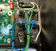
Both by the same builder...I'm so confused...
But does it really matter which "side" of the fuse holder you have hot? Is there a possibility that you could get in contact with a live portion while changing fuses? If there is going to be a real danger I can change things (would be a pain in the arse but if necessary...) but would like to really understand the why.
And Eric's observation about the lack of slack in the line fuse was spot on...it works as it but induces a little "flex" in the ISO socket when you insert/remove the fuse so I am going to change that wire for a longer one.
Just to clarify, the top picture was posted in one of my threads, but not from one of my builds.
The side terminal of the fuse holder is tied to the center ring as shown in the picture below on the Left.
If you remove the fuse holder cap, that center ring is finger accessible and has 100V DC if the tabs are tied together like the factory.

The side terminal of the fuse holder is tied to the center ring as shown in the picture below on the Left.
If you remove the fuse holder cap, that center ring is finger accessible and has 100V DC if the tabs are tied together like the factory.

Pulpmillguy
Journeyman
OK, so that does put the 100V right there by the opening and ready to get your finger if you should stick it in there...Just to clarify, the top picture was posted in one of my threads, but not from one of my builds.
The side terminal of the fuse holder is tied to the center ring as shown in the picture below on the Left.
If you remove the fuse holder cap, that center ring is finger accessible and has 100V DC if the tabs are tied together like the factory.

But if you connect to the tip, when you are inserting the fuse you also run the risk of getting a little bite...
So basically you are screwed if you do, screwed if you don't...just be careful when changing fuses.
I disagree, by design if wired correctly, the fuse does not make contact with the tip until the cap and assembly is finger safe.But if you connect to the tip, when you are inserting the fuse you also run the risk of getting a little bite...
In the picture below, the fuse has not yet contacted the tip.

Pulpmillguy
Journeyman
Mine seem to make contact a little sooner and if you tried you might get bit but nevertheless I'm reworking the lines to power up the tip as you recommended. I like your little loop in the connecting wire, not sure mine is going to look as neat but we'll see how they turn out.I disagree, by design if wired correctly, the fuse does not make contact with the tip until the cap and assembly is finger safe.
In the picture below, the fuse has not yet contacted the tip.

Pulpmillguy
Journeyman
Well, checked around town and nobody from auto parts stores to industrial supply houses had the shoulder bushings for the transformer isolation. I found some on Amazon and Ebay but the best I could do pricewise was some dude in France and a pack of 10 would cost about €12...delivered sometime in December. While I was looking around town, I did find some 25mm diameter PTFE stock...and I have a lathe...so I made my own bushings.
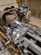
I stole Mark's idea about using the heat shrink on the bolts and think it is going to work out quite nicely. I made the bushings different lengths so I could get engagement in the transformer core instead of the caps. I epoxy filled the corners and drilled the holes slightly oversize from the bushings to account for any deviations there might be...the bushings are a quite tight fit in the core.

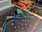
I put a little more heat and solder in the main cap lugs as Joe suggested and added some slack in the incoming AC line and am reworking the feeds to the DC fuses. (thanks, Eric)
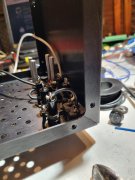
Drilled the heat sinks to 5mm to make sure there is clearance around the transistor leads. Had to MacGyver a chamfering tool as I didn't have a jobber length that would reach to the bottom of the fins. I know some of the holes look a little "wavy" but the top edge is smooth as a baby's butt. If I had thought about it I would have gotten a jobber length bit and drilled them from the transistor side so there wouldn't be any burr. (probably would have deburred the holes anyway just to be on the safe side) Still need to do a final cleaning (man that silicone paste is hell but brake cleaner works pretty well on it...wonder how well it would work for cleaning circuit boards or would it leave some residue?)
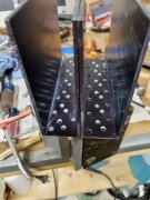
And now, for the inspirational moment...sweet dreams


I stole Mark's idea about using the heat shrink on the bolts and think it is going to work out quite nicely. I made the bushings different lengths so I could get engagement in the transformer core instead of the caps. I epoxy filled the corners and drilled the holes slightly oversize from the bushings to account for any deviations there might be...the bushings are a quite tight fit in the core.

I put a little more heat and solder in the main cap lugs as Joe suggested and added some slack in the incoming AC line and am reworking the feeds to the DC fuses. (thanks, Eric)


Drilled the heat sinks to 5mm to make sure there is clearance around the transistor leads. Had to MacGyver a chamfering tool as I didn't have a jobber length that would reach to the bottom of the fins. I know some of the holes look a little "wavy" but the top edge is smooth as a baby's butt. If I had thought about it I would have gotten a jobber length bit and drilled them from the transistor side so there wouldn't be any burr. (probably would have deburred the holes anyway just to be on the safe side) Still need to do a final cleaning (man that silicone paste is hell but brake cleaner works pretty well on it...wonder how well it would work for cleaning circuit boards or would it leave some residue?)

And now, for the inspirational moment...sweet dreams

Nice grab...Well, checked around town and nobody from auto parts stores to industrial supply houses had the shoulder bushings for the transformer isolation. I found some on Amazon and Ebay but the best I could do pricewise was some dude in France and a pack of 10 would cost about €12...delivered sometime in December. While I was looking around town, I did find some 25mm diameter PTFE stock...and I have a lathe...so I made my own bushings.
View attachment 78120
I stole Mark's idea about using the heat shrink on the bolts and think it is going to work out quite nicely. I made the bushings different lengths so I could get engagement in the transformer core instead of the caps. I epoxy filled the corners and drilled the holes slightly oversize from the bushings to account for any deviations there might be...the bushings are a quite tight fit in the core.
View attachment 78121
I put a little more heat and solder in the main cap lugs as Joe suggested and added some slack in the incoming AC line and am reworking the feeds to the DC fuses. (thanks, Eric)
View attachment 78122
View attachment 78123
Drilled the heat sinks to 5mm to make sure there is clearance around the transistor leads. Had to MacGyver a chamfering tool as I didn't have a jobber length that would reach to the bottom of the fins. I know some of the holes look a little "wavy" but the top edge is smooth as a baby's butt. If I had thought about it I would have gotten a jobber length bit and drilled them from the transistor side so there wouldn't be any burr. (probably would have deburred the holes anyway just to be on the safe side) Still need to do a final cleaning (man that silicone paste is hell but brake cleaner works pretty well on it...wonder how well it would work for cleaning circuit boards or would it leave some residue?)
View attachment 78124
And now, for the inspirational moment...sweet dreams
View attachment 78125
Your shoulders may be too thick on your Teflon shoulder washers. Check the clearance of the nuts to the body of the bulk capacitors in the cradles. Sometimes they hit and sometimes you are good.
Pulpmillguy
Journeyman
My understanding of the stack-up puts the Teflon washers between the transformer and the chassis so the thicker shoulders shouldn't make any difference (other than making the bolts appear shorter) or do I understand wrong?Nice grab...
Your shoulders may be too thick on your Teflon shoulder washers. Check the clearance of the nuts to the body of the bulk capacitors in the cradles. Sometimes they hit and sometimes you are good.
You will need to electrically isolate the nut and washer from the inside of the housing if placing the bushing on the outside between the housing cradle.
The important part is isolating the bolt from chassis ground, not the transformer or cradle.
The important part is isolating the bolt from chassis ground, not the transformer or cradle.
Pulpmillguy
Journeyman
OK, now I'm confused  ...so in addition to electrically isolating the transformer/transformer housing from the chassis and the bolts, I need to also isolate the bolts from the chassis? My plan was to electrically isolate the transformer/transformer housing from the chassis using the Teflon bushing (the long ones) between the aluminum end cap of the transformer and the chassis. The bolts would be electrically isolated at the other end using the short bushings. Are you saying that by having the bolts in contact with the chassis will cause them to act like antennas and pick up noise from the transformer core? Is this why I need to isolate them? Hey, cut me some slack here, as I said I'm a mechanical engineer, not a sparky so some (most) of this stuff is new to me.
Especially your last statement regarding "most important part is isolating the bolt from chassis ground, not the transformer" kinda threw me.
Especially your last statement regarding "most important part is isolating the bolt from chassis ground, not the transformer" kinda threw me.
Pulpmillguy
Journeyman
OK, problem solved...just a quick trip back to the lathe and machine a shoulder in the shoulder...(it was 5mm thick to start with) and then top it off with a Teflon washer...You will need to electrically isolate the nut and washer from the inside of the housing if placing the bushing on the outside between the housing cradle.
The important part is isolating the bolt from chassis ground, not the transformer or cradle.
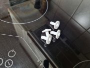
But I'm still curious about why basically everything has to be isolated from each other...
At a high level, the bolts pass through the transformer core and eddy currents are induced into the bolts.But I'm still curious about why basically everything has to be isolated from each other...
The intent of this mod is to electrically isolate the bolts from chassis ground to prevent the eddy currents from potentially causing noise and offsets within chassis ground.
This is common practice in many sensitive test and measurement equipment.
The transformer mounting bolt bushings are typically mounted on the outside of the transformer bell and inside the chassis housing. I have multiple pictures on each of my build threads showing the bushings under the bolt head and under the nut.
The stack up is as follows (from the outside in):
After mounting the transformer to the chassis, place the following:

- Bolt
- Bushing
- Washer
After mounting the transformer to the chassis, place the following:
- Washer
- Bushing (through washer, chassis, cradle, transformer core)
- Nut

Pulpmillguy
Journeyman
You mean like this?At a high level, the bolts pass through the transformer core and eddy currents are induced into the bolts.
The intent of this mod is to electrically isolate the bolts from chassis ground to prevent the eddy currents from potentially causing noise and offsets within chassis ground.
This is common practice in many sensitive test and measurement equipment.
The transformer mounting bolt bushings are typically mounted on the outside of the transformer bell and inside the chassis housing. I have multiple pictures on each of my build threads showing the bushings under the bolt head and under the nut.
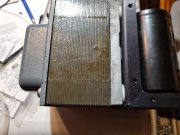
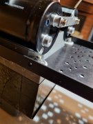
Pulpmillguy
Journeyman
Hang on a sec...do you put the transformer cradle directly in contact with the amp chassis? You don't say anything about putting a bushing between them so you are connecting them electrically. I checked my set-up and I don't get anything between chassis-bolt-transformer-chassis so I think I have accomplished the goal, right?The stack up is as follows (from the outside in):
Insert above into the transformer bell.
- Bolt
- Bushing
- Washer
After mounting the transformer to the chassis, place the following:
See below for pictures (the bushing is Black):
- Washer
- Bushing (through washer, chassis, cradle, transformer core)
- Nut

What you have implemented should work, as long as the bolts are isolated (the pictures don't show under the bolt head).
I do not isolate the transformer core or cradle from chassis.
Each plate within the transformer lamination stack is isolated to help minimize eddy currents.
I do not isolate the transformer core or cradle from chassis.
Each plate within the transformer lamination stack is isolated to help minimize eddy currents.

