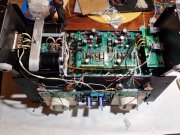
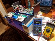
And the journey begins...

Joined
May 17, 2023
Messages
306
Location
Finland via the deep south
Tagline
Details, details
#84
Hey guys, ran into a little problem (well, actually two of them but solved one) on the build. The input selector switch has got a crappy connection on one channel and I need to replace it. Does anybody have a part number for this little guy? I am already ordering a thermal cut-out switch (I discovered one was bad) from Mauser so one of their P/N would be just dandy...
 
Joined
May 17, 2023
Messages
306
Location
Finland via the deep south
Tagline
Details, details
#88
Did a little more wiring today, getting so damn close but now I need to wait another friggin' week for fuses...how I love living in the middle of nowhere...
20231111_215431.jpg

Got everything ready for commissioning of power supply and backplane but can't find 1A fuses and I'm missing a 5A line fuse. That 1/4" x 1" fuse size that PL used isn't common over here so I had to order some from Mouser :mad:

At least it gives me some time to wire everything up to make sure it is going to fit (I know I will have to take it apart for commissioning but that's OK).

Say Good Night, Gracie...


Bikini babe.png
 
Joined
May 17, 2023
Messages
306
Location
Finland via the deep south
Tagline
Details, details
#89
Making preparations for powering up and have been reading all of the bringing up instructions that Joe provided and it seems that this is the recommended order (or at least what I am planning):

  1. With B+ and B- fuses pulled (both main fuses and small fuses on backplanes), power up the transformer and bulk caps. Check B+ and B- voltages. If everything OK proceed to next step.
  2. Install fuses and power up backplanes with no pre-drivers or output transistors installed. If everything OK, proceed to next step.
  3. Install pre-drivers, the 10K resistor from channel output to ground, pull the single point ground wire and check for shorts. If everything is OK, proceed to next step. (When do I remove the 10K resistor? Is it now or after I have all of the output transistors installed? I see where you need to keep the single point ground wire disconnected until you have all of the outputs installed but I don't see anywhere that you tell to remove this resistor...)
  4. Power up the backplane with the pre-drivers installed, if everything is OK then proceed to the next step.
  5. Connect the control board and power it up. Check that everything is OK, set the bias and then power down and proceed to the next step.
  6. Install the first row of driver output transistors, power up, hopefully everything is OK and then recheck bias.
  7. Power down, rinse and repeat until all of the output transistors are installed. Before I power it up with ALL of the output transistors installed, I should reconnect the single point ground.
Let's just hope that I can get all the way to step 7 without letting the magic smoke out...

I assume the reason you delay connecting the DC protection board until the end is to keep the number of things to watch at a minimum during the bringing up of the backplane or does having it connected screw with things? Just asking as I have mine installed but if I have to remove it for commissioning I will.
 
Joined
May 17, 2023
Messages
306
Location
Finland via the deep south
Tagline
Details, details
#90
It's alive...
20231112_181825.jpg

Now I really need to wait for the fuses to get here as I found out what happens when you use a 125V fuse in a 230V application (I stole one of the DC fuses and used it for the incoming line). When I first fired it up I used the DBT and it worked like a champ. Then I started wondering why I'm only getting +/-100VDC when before I was getting like +/-104VDC...was it the DBT so I pulled it out of the circuit but when I hit the power the fuse blew...that ol' inrush will get you every time.

Anyway, at least I know the power supply works (and those blue LED lights on the front panel look so bad-ass) and I even herd the relays on the DC protection board click after power-up so good feelings there.

Now as they say in Indonesia "waiting, waiting..."
20231112_182749.jpg
 

Hexis22

Chief Journeyman
Joined
Dec 28, 2022
Messages
675
Location
Wisconsin
#91
Your fuse dilemma, although compounded by your location, is why most replace all fuse holders to accommodate AGC size fuses.

I recognize that picture on your laptop in the background...
 
Last edited:
Joined
May 17, 2023
Messages
306
Location
Finland via the deep south
Tagline
Details, details
#92
Your fuse dilemma, although compounded by your location, is why most replace all fuse holders to accommodate AGC size fuses.

I recognize that picture on your laptop in the background...
You know...I have been thinking about that but you know what happens in most projects...great idea but shitty timing.

Besides, I have a shitload of fuses on the way (along with two new thermal cut-outs) so might as well use them.
 
Joined
May 17, 2023
Messages
306
Location
Finland via the deep south
Tagline
Details, details
#93
Your fuse dilemma, although compounded by your location, is why most replace all fuse holders to accommodate AGC size fuses.

I recognize that picture on your laptop in the background...
I'll bet you do recognize that picture...lots of good reference material in your old threads.

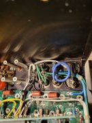
I tried but couldn't make the loops as sexy as yours...
20231112_201146.jpg
 

Gepetto

Administrator
Staff member
Joined
May 15, 2011
Messages
13,927
Location
Sterling, MA
Tagline
Old 'Arn Enthusiast
#94
You know...I have been thinking about that but you know what happens in most projects...great idea but shitty timing.

Besides, I have a shitload of fuses on the way (along with two new thermal cut-outs) so might as well use them.
Hi Robbie, you could have ordered all that stuff with your original order, I have all of that in stock, many folks ask for the fuses, fuseholders, thermal cutouts, etc. so I keep them in stock.
 

MarkWComer

Veteran and General Yakker
Joined
Nov 1, 2014
Messages
3,486
Location
Gaston, SC
Tagline
Victim of the record bug since age five
#95
Hi Robbie, you could have ordered all that stuff with your original order, I have all of that in stock, many folks ask for the fuses, fuseholders, thermal cutouts, etc. so I keep them in stock.
Robbie: don’t feel bad- I once ordered the whole kit except for the output transistors, got them separately from Mouser. I could have saved some time.

BTW- download the Audacity application on yer laptop- it makes a convenient frequency generator to check your DC protection circuit and calibrate your display LEDs.
 
Joined
May 17, 2023
Messages
306
Location
Finland via the deep south
Tagline
Details, details
#96
If I had known that the GD fuses would be so damn hard to find here I would have either ordered them with the other components or I would have just changed the holders...

But what I really need to know is when do I remove that 10K resistor from the output...
1699855745342.png
 

Gepetto

Administrator
Staff member
Joined
May 15, 2011
Messages
13,927
Location
Sterling, MA
Tagline
Old 'Arn Enthusiast
#97
If I had known that the GD fuses would be so damn hard to find here I would have either ordered them with the other components or I would have just changed the holders...

But what I really need to know is when do I remove that 10K resistor from the output...
View attachment 78292
14. Install ONLY the bottom most row of transistors, starting with the transformer side an MJ21196
in first column, then MJ21195 in second column, then MJ21196 in third column, then MJ21195
in fourth column.
15. Temporarily attach a 10K ohm resistor between each channel output and DC ground.
16. With the one wire from the DC ground bus bar to the chassis standoff tie point temporarily
removed, test for no shorts from DC ground or the B+/B- rails to the chassis. Test each
transistor can for no shorts to the chassis as well.
17. Bring up wired bare chassis with Variac and DBT.
18. Gradually apply AC voltage using the Variac and DBT. Check all voltages for proper values, no
shorts, no blown fuses, etc.
19. Check for 0V at each channel output. If all OK, you can now remove the temporary 10K ohm
resistors.


Added this note to the bring up instructions
 
Joined
May 17, 2023
Messages
306
Location
Finland via the deep south
Tagline
Details, details
#98
14. Install ONLY the bottom most row of transistors, starting with the transformer side an MJ21196
in first column, then MJ21195 in second column, then MJ21196 in third column, then MJ21195
in fourth column.
15. Temporarily attach a 10K ohm resistor between each channel output and DC ground.
16. With the one wire from the DC ground bus bar to the chassis standoff tie point temporarily
removed, test for no shorts from DC ground or the B+/B- rails to the chassis. Test each
transistor can for no shorts to the chassis as well.
17. Bring up wired bare chassis with Variac and DBT.
18. Gradually apply AC voltage using the Variac and DBT. Check all voltages for proper values, no
shorts, no blown fuses, etc.
19. Check for 0V at each channel output. If all OK, you can now remove the temporary 10K ohm
resistors.


Added this note to the bring up instructions
I was wondering as the bring up instructions that you sent me don't have that...
1699897033256.png

Thanks for the clarification. I was wondering if they provided some sort of "load" for the pre-drivers...but then again 10K isn't much.
 

Gepetto

Administrator
Staff member
Joined
May 15, 2011
Messages
13,927
Location
Sterling, MA
Tagline
Old 'Arn Enthusiast
#99
I was wondering as the bring up instructions that you sent me don't have that...
View attachment 78293

Thanks for the clarification. I was wondering if they provided some sort of "load" for the pre-drivers...but then again 10K isn't much.
I added the note to the bring up instructions just now. Future recipients will have this added note.

All transistors, no matter how good will have a small amount of leakage current. The 10K ensures that this leakage is indeed small. If you got an appreciable voltage on the 10K resistor, it would indicate you had a leaker, which you would want to debug and find out which was the culprit.
 
Joined
May 17, 2023
Messages
306
Location
Finland via the deep south
Tagline
Details, details
OK, Mouser ships from Czech Republic...got the stuff today!

Now I have powered up the backplanes only and am getting about 0,9 VDC on the output...is this normal and it is OK to proceed with installing the pre-drivers or is there something that I need to investigate first?

No smoke or funny smells so I am hoping that everything is OK so far...please advise.
 
Top