J!m
Veteran and General Yakker
Most, but not all...
Most, but not all...
not only unplug it but also wait till those bad-boy filter caps discharge...The smart ones who don't like to get SHOCKED do
I think I solved my own problem again...The smart ones who don't like to get SHOCKED do
Works for me...I'm bypassing the input level pots also so the cleaner the signal the better.Many of us bypassed it as it is unneeded. I used the old switch as a hole filler.


You know...I have been thinking about that but you know what happens in most projects...great idea but shitty timing.Your fuse dilemma, although compounded by your location, is why most replace all fuse holders to accommodate AGC size fuses.
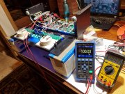
I recognize that picture on your laptop in the background...
I'll bet you do recognize that picture...lots of good reference material in your old threads.Your fuse dilemma, although compounded by your location, is why most replace all fuse holders to accommodate AGC size fuses.
I recognize that picture on your laptop in the background...

Hi Robbie, you could have ordered all that stuff with your original order, I have all of that in stock, many folks ask for the fuses, fuseholders, thermal cutouts, etc. so I keep them in stock.You know...I have been thinking about that but you know what happens in most projects...great idea but shitty timing.
Besides, I have a shitload of fuses on the way (along with two new thermal cut-outs) so might as well use them.
Robbie: don’t feel bad- I once ordered the whole kit except for the output transistors, got them separately from Mouser. I could have saved some time.Hi Robbie, you could have ordered all that stuff with your original order, I have all of that in stock, many folks ask for the fuses, fuseholders, thermal cutouts, etc. so I keep them in stock.
14. Install ONLY the bottom most row of transistors, starting with the transformer side an MJ21196If I had known that the GD fuses would be so damn hard to find here I would have either ordered them with the other components or I would have just changed the holders...
But what I really need to know is when do I remove that 10K resistor from the output...
View attachment 78292
I was wondering as the bring up instructions that you sent me don't have that...14. Install ONLY the bottom most row of transistors, starting with the transformer side an MJ21196
in first column, then MJ21195 in second column, then MJ21196 in third column, then MJ21195
in fourth column.
15. Temporarily attach a 10K ohm resistor between each channel output and DC ground.
16. With the one wire from the DC ground bus bar to the chassis standoff tie point temporarily
removed, test for no shorts from DC ground or the B+/B- rails to the chassis. Test each
transistor can for no shorts to the chassis as well.
17. Bring up wired bare chassis with Variac and DBT.
18. Gradually apply AC voltage using the Variac and DBT. Check all voltages for proper values, no
shorts, no blown fuses, etc.
19. Check for 0V at each channel output. If all OK, you can now remove the temporary 10K ohm
resistors.
Added this note to the bring up instructions

I added the note to the bring up instructions just now. Future recipients will have this added note.I was wondering as the bring up instructions that you sent me don't have that...
View attachment 78293
Thanks for the clarification. I was wondering if they provided some sort of "load" for the pre-drivers...but then again 10K isn't much.
