A TEAC question for Sam re an A2300SD

62vauxhall

Veteran and General Yakker
Joined
May 14, 2014
Messages
2,287
Location
Southwest Kootenays BC
Tagline
No such things as bad days, just bad moments
#21
What 5 watt bulbs? The meter lamps are 8 V at 55mA and that is only .44W each so less than 1watt consumption. I do not know of any 5 watta bulbs in these units.
The 24 Vdc supply feeds the Audio section and the Bias Oscillator not the lamps. The lamps are fed from a seperate 6.3Vac tap off the transformer- you may have this unit wired up by a Yahoo technician and so you need to put it back the way it was designed. If you open up the fuse link in the transformer then you will be opening up and trying to do surgery on a transformer which I bet will not be fun- I have done them but I would rather avoid such work. The amount of current the deck using at most would be in record mode but the LM7824 propertly heat sinked will not ge that hot from what is normally drawn from the supply.
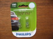
The two 5 watt 12 volt bulbs in series are automotive bulbs, probably for interior dome lights. Nothing to do with the deck. I obtained them for testing purposes only - the 24 volt output of the power supply.
IMG_4764.JPG
 

62vauxhall

Veteran and General Yakker
Joined
May 14, 2014
Messages
2,287
Location
Southwest Kootenays BC
Tagline
No such things as bad days, just bad moments
#22
In the one picture above there are even uninsulated resistors touching and mounted wrong according to the silkscreen on the Board. There seems to be a lot of mistakes going on in this unit. If you are going to mount resistors with that much lead then put a PVC jacket on them but there is no reason to all such long leads to exist in the use of the resistors.
My thoughts exactly which is why I am saying this is a load problem, not a regulator problem. If the load was right, the transistor would probably be loafing.

If it normally ran that hot (as it has been before blowing) the PCB material would have turned brown. It wasn't that way in the photos Gary shared.
There is a story behind that board in the photo.

It is the original board to this deck but damaged from several wire wound resistors that incinerted. A problem that existed when I bought the deck in 2014.

I sourced a replacement board on ebay and it is that board, not the original, that is in the deck now. I kept the old one for reference. It was just easier to photograph the damaged one because it was at hand rather than to take a pic of the board that is in place in the deck. The intention was only to show how transistor Q1 was attached - flat against the board material.

As things turned out, replacing the board alleviated the burning reistor issue but that's when the transport ceased to function. A coincidence I suppose that the faulty micro switch responsible for that chose to becme problematic at the same time the replacement board was wired up.
 

Gepetto

Administrator
Staff member
Joined
May 15, 2011
Messages
13,535
Location
Sterling, MA
Tagline
Old 'Arn Enthusiast
#23
There is a story behind that board in the photo.

It is the original board to this deck but damaged from several wire wound resistors that incinerted. A problem that existed when I bought the deck in 2014.

I sourced a replacement board on ebay and it is that board, not the original, that is in the deck now. I kept the old one for reference. It was just easier to photograph the damaged one because it was at hand rather than to take a pic of the board that is in place in the deck. The intention was only to show how transistor Q1 was attached - flat against the board material.

As things turned out, replacing the board alleviated the burning reistor issue but that's when the transport ceased to function. A coincidence I suppose that the faulty micro switch responsible for that chose to becme problematic at the same time the replacement board was wired up.
And that board in the photo is not brown behind the regulator transistor. That cheap paper phenolic board the Japanese companies use would have been toasty brown by now if subjected to 60C continuously.
 

62vauxhall

Veteran and General Yakker
Joined
May 14, 2014
Messages
2,287
Location
Southwest Kootenays BC
Tagline
No such things as bad days, just bad moments
#24
Joe, if your thought was that I obtained a newly made replacement board, I should have elaborated. The board sourced through ebay was a TEAC part, salvaged from a deck being parted out.

Does your 60C comment imply that a transistor reaching that temperature in this application would be the norm?
 

Gepetto

Administrator
Staff member
Joined
May 15, 2011
Messages
13,535
Location
Sterling, MA
Tagline
Old 'Arn Enthusiast
#25
Joe, if your thought was that I obtained a newly made replacement board, I should have elaborated. The board sourced through ebay was a TEAC part, salvaged from a deck being parted out.

Does your 60C comment imply that a transistor reaching that temperature in this application would be the norm?
No Gary, like Sam also thinks, that transistor in the regulator circuit is likely loafing and running only slightly warm. 60C is 10C above the human threshold of pain, where you cannot keep your finger on it.

You indicated that the photo was of your original board, well used. If that transistor spent its life running at 60C, you would have seen a nice char spread around that transistor on the paper phenolic board. There is no discoloration.

Also you replaced it with a transistor much beefier than the original and it blew quickly due to overtemp. That should not have occurred. Something downstream is pulling too much current (a load problem). You have to find and fix that load problem.
 

62vauxhall

Veteran and General Yakker
Joined
May 14, 2014
Messages
2,287
Location
Southwest Kootenays BC
Tagline
No such things as bad days, just bad moments
#26
The only thing pulling current was those two 12 volt bulbs in series. Anything "downstream" was disconnected. As mentioned, the current draw of those two bulbs is 310 Ma.

I have now individually checked current drawn by each of the red wires feeding various sections of the deck and it is minimal.

Collecftive current drawn with all of the red wires connected was about 70 Ma. Considerably less than what the two bulbs consume.

Temperature of the LM7824 (on a heatsink),with that load of 70 Ma topped out at 30 degrees C.

Would that be considered acceptible?
 

Skywavebe

Chief Journeyman
Joined
Jun 13, 2010
Messages
725
Location
Bensenville, IL
Tagline
Work too much
#27
I really do not see the logic in putting automotive blubs on this deck as there is no reason for it. This just then confuses the issue. I would just fix the deck and forget about hooking up extraneous loads. The Bias oscillator and some caps on the audio cards might be shorted. Most the time a bias oscillator transistor can be shorted depending on where it is. They move those around depending on design. I seem to remember that the bias adjustments are on the power supply on the A2300SD due to lack of space. A low temperature situation is correct but we do not know the size of heat sink you upgraded to as that can also affect it's result. Low temps is what I would want.
 

62vauxhall

Veteran and General Yakker
Joined
May 14, 2014
Messages
2,287
Location
Southwest Kootenays BC
Tagline
No such things as bad days, just bad moments
#28
I really do not see the logic in putting automotive blubs on this deck as there is no reason for it. This just then confuses the issue. I would just fix the deck and forget about hooking up extraneous loads. The Bias oscillator and some caps on the audio cards might be shorted. Most the time a bias oscillator transistor can be shorted depending on where it is. They move those around depending on design. I seem to remember that the bias adjustments are on the power supply on the A2300SD due to lack of space. A low temperature situation is correct but we do not know the size of heat sink you upgraded to as that can also affect it's result. Low temps is what I would want.
Yes, this SD version has the power supply and bias oscillator on the same board. I am fairly certain it would have been much easier for me and less time consuming if that were not so. Nearly 7 years have past since I acquired the deck in August 2014 and first attempted to get it working.

Using two 12 volt bulbs in series was someone's suggestion that I took to evaluate the power supply.

The heatsink I chose was based on an example photo sent by that same person who also suggested using the LM7824.

IMG_4774.JPG
 

Gepetto

Administrator
Staff member
Joined
May 15, 2011
Messages
13,535
Location
Sterling, MA
Tagline
Old 'Arn Enthusiast
#29
The only thing pulling current was those two 12 volt bulbs in series. Anything "downstream" was disconnected. As mentioned, the current draw of those two bulbs is 310 Ma.

I have now individually checked current drawn by each of the red wires feeding various sections of the deck and it is minimal.

Collecftive current drawn with all of the red wires connected was about 70 Ma. Considerably less than what the two bulbs consume.

Temperature of the LM7824 (on a heatsink),with that load of 70 Ma topped out at 30 degrees C.

Would that be considered acceptible?
So what changed from when you had the transistor in the original circuit? They should both perform identically from a dissipation perspective.

You had indicated before that it got so hot that it destroyed itself
 

Skywavebe

Chief Journeyman
Joined
Jun 13, 2010
Messages
725
Location
Bensenville, IL
Tagline
Work too much
#30
The heat sink looks good but I don't see any isolation hardware from screw to sink and if this will touch metal that will still be shorting. Does the tab of semiconductor ohm out open to the sink? The Silpad is not the only thing you need.
 

62vauxhall

Veteran and General Yakker
Joined
May 14, 2014
Messages
2,287
Location
Southwest Kootenays BC
Tagline
No such things as bad days, just bad moments
#31
So what changed from when you had the transistor in the original circuit? They should both perform identically from a dissipation perspective.

You had indicated before that it got so hot that it destroyed itself

The heat damaged transistor got hot because I was not monitoring it's temperature. It's designation was Q1 and had a counterpart designated Q2. Q2 was never replaced just pulled and checked several times and each time it appeared OK. A speculation was that Q2 may have been faulty under load thereby affecting Q1.

Contributing factors might have been the excess current draw of the those two bulbs and that I temporarily did not anchor the Q1 transistor to the board so nothing to act as a heatsink - it was free standing.
 

62vauxhall

Veteran and General Yakker
Joined
May 14, 2014
Messages
2,287
Location
Southwest Kootenays BC
Tagline
No such things as bad days, just bad moments
#32
The heat sink looks good but I don't see any isolation hardware from screw to sink and if this will touch metal that will still be shorting. Does the tab of semiconductor ohm out open to the sink? The Silpad is not the only thing you need.
Yes, it ohms open to the heatsink (OL). I have the necessary hardware (somewhere) but when I ordered the heatsink, I just got the insulating kit as well.

IMG_4775.JPG
 

Skywavebe

Chief Journeyman
Joined
Jun 13, 2010
Messages
725
Location
Bensenville, IL
Tagline
Work too much
#33
OK, Was just making sure to keep from there being more sparks. Some people have these kinds of heat sinks laying around and or taken off other equipment so the PCB pins made me think it was a reclaimed part. Good for you that the deck is being modernized.
 

62vauxhall

Veteran and General Yakker
Joined
May 14, 2014
Messages
2,287
Location
Southwest Kootenays BC
Tagline
No such things as bad days, just bad moments
#34
The heatsink is JP Welded to the chassis. Below the motors and positioned so it catches the feeble breeze generated by the sort of fan on the capstan motor.

IMG_4776.JPG

After a brief (but not too brief) AW F**K moment, when discovering and reconnecting a stray wire and the transport wouldn't work, I learned that solonoids and motors do not respond well to AC fed through a dim bulb tester.

But it works now. Plays, records, FF's REW's....all that good stuff and it only took 7 years. This thing almost became a parts donor a few times.

Thanks to all as usual for the insights, tips and suggestions.
 
Top