A TEAC question for Sam re an A2300SD

62vauxhall

Veteran and General Yakker
Joined
May 14, 2014
Messages
2,321
Location
Southwest Kootenays BC
Tagline
No such things as bad days, just bad moments
#1
What voltage should be present at the Base pad of Q1?

The MJE15032G I recently installed there failed. After multiple 2SD288's failed several years ago because of grounded Collectors, I thought this latest transistor without being shorted was the answer.

As per the service manual, 23 volts was obtained at tab #36 so I thought things were rosy. A couple of days later, when I measured again, there were a few hundred millivolts and the new Q1 was too hot to handle.

I removed the MJE15032G and checked it with a DMM and it's a goner. That made me wonder what voltage it was seeing and I measured 41 volts and it's Base pad. The schematic does not help as I've not seen any voltages printed on it. I thought the most I'd measure was 23/34 volts.
 

Gepetto

Administrator
Staff member
Joined
May 15, 2011
Messages
14,019
Location
Sterling, MA
Tagline
Old 'Arn Enthusiast
#2
What voltage should be present at the Base pad of Q1?

The MJE15032G I recently installed there failed. After multiple 2SD288's failed several years ago because of grounded Collectors, I thought this latest transistor without being shorted was the answer.

As per the service manual, 23 volts was obtained at tab #36 so I thought things were rosy. A couple of days later, when I measured again, there were a few hundred millivolts and the new Q1 was too hot to handle.

I removed the MJE15032G and checked it with a DMM and it's a goner. That made me wonder what voltage it was seeing and I measured 41 volts and it's Base pad. The schematic does not help as I've not seen any voltages printed on it. I thought the most I'd measure was 23/34 volts.
You need to heat sink the poor devil. That dissipation has to go somewhere. You told us in the past, it was heat sunk to the chassis but you opted away from that route.

Have you posted a schematic? You should be able to dump some of that dissipation into a series resistor on the collector side of the transistor if we know what the circuit looks like.
 

62vauxhall

Veteran and General Yakker
Joined
May 14, 2014
Messages
2,321
Location
Southwest Kootenays BC
Tagline
No such things as bad days, just bad moments
#3
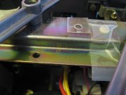
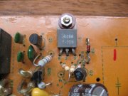
Thanks Joe. I used the original board and original transistor for the pic.

How that transistor was mounted did not involve what I would consider a conventional heat sink. It lay flush against the PC board with a mica wafer sandwiched in between. A machine screw passed through the hole with an insulating washer and was attached as shown by a nut and fiber washer.

The 2nd photo shows the hole that the machine screw passes through on the opposite side, a chassis component. So nothing metal in direct contact with the collector plate, heat absorbed and dissipated by the circuit board material? To my mind, that does not seem very effective or that transistor was not expected to get that warm.

That board is held to the chassis by three screws. That transistor's machine screw is the middle one. Unless that machine screw is capable of transferring heat yet be electrically isolated from the chassis, I don't understand why TEAC designed it that way. Two screws, one on each side of the middle hole should have been sufficient.

The mica wafer & insulating washer are shown in the 2nd photo as well.

IMG_4755.JPG

IMG_4756.JPG

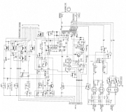
There are two schematics in the HiFi Engine service manual. Both look identical to me so I've only included one.

file:///C:/Users/Acer/Downloads/hfe_teac_a-2300sd_service_en%20(9).pdf

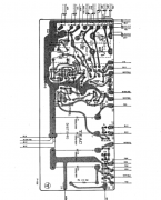
The power supply in this A2300SD model does not have a dedicated circuit board. It is incorporated into the Bias Oscilator board.

TEAC A2300SC schematic.PNG

TEAC bias oscillator component diagram.PNG
 

Gepetto

Administrator
Staff member
Joined
May 15, 2011
Messages
14,019
Location
Sterling, MA
Tagline
Old 'Arn Enthusiast
#4
Thanks Joe. I used the original board and original transistor for the pic.

How that transistor was mounted did not involve what I would consider a conventional heat sink. It lay flush against the PC board with a mica wafer sandwiched in between. A machine screw passed through the hole with an insulating washer and was attached as shown by a nut and fiber washer.

The 2nd photo shows the hole that the machine screw passes through on the opposite side, a chassis component. So nothing metal in direct contact with the collector plate, heat absorbed and dissipated by the circuit board material? To my mind, that does not seem very effective or that transistor was not expected to get that warm.

That board is held to the chassis by three screws. That transistor's machine screw is the middle one. Unless that machine screw is capable of transferring heat yet be electrically isolated from the chassis, I don't understand why TEAC designed it that way. Two screws, one on each side of the middle hole should have been sufficient.

The mica wafer & insulating washer are shown in the 2nd photo as well.

View attachment 49371

View attachment 49372

There are two schematics in the HiFi Engine service manual. Both look identical to me so I've only included one.

file:///C:/Users/Acer/Downloads/hfe_teac_a-2300sd_service_en%20(9).pdf

The power supply in this A2300SD model does not have a dedicated circuit board. It is incorporated into the Bias Oscilator board.

View attachment 49373

View attachment 49374
Pretty lame approach to design. Hard to tell if it isn't something downstream pulling too much load current. Can't read the schem and it won't allow it to be blown up. The TO AMP box on the far right can be pulling all kinds of abnormal current, which is directly fed by this transistor. My guess is you are chasing the symptom, not the cause. They already appear to have a 3.3 ohm resistor in series with the collector to dissipate some of the power.
 

Skywavebe

Chief Journeyman
Joined
Jun 13, 2010
Messages
725
Location
Bensenville, IL
Tagline
Work too much
#5
Resistor in series are protection or current limiting. Many people know enough about electronics to make them dangerous which is what they become.
The transistor is heat sinked and isolated with Mica- Mica is an old cheap low tech way to do things put a Silpad from off E bay and then the right mounting hardware. If the voltage is being drawn down at some point think about putting a current limiting circuit in- that way when something goes bad which I suspect is a intermittent shorting cap, then the foldback system will protect the regulator transistor. The pinciple is easy to understand.
Personally if a small transistor gets hot there is always the option to install a larger one that can handle a lot more current and heat but of course the current limit idea is still a good one. Some math and ohms law is involved. I often think about enhancing the heat sink in the X1000R but there is really limited room and the heat has to go somewhere. A fan and a vent tube would be desirable but these bring cost and maintenance items with them. Like the guy in Thailand that works his deck at 100 degrees plus temps- the case is off with a fan blowing on the unit. I guess they don't get a lot of cold weather down there. So rather than use all the brain power to find where the fault is that may hide from you why not just recap the whole thing then look for a problem? It need new caps anyway.
 

Skywavebe

Chief Journeyman
Joined
Jun 13, 2010
Messages
725
Location
Bensenville, IL
Tagline
Work too much
#6
The circuit is usually a very basic zener diode referenced voltage regulator. You could measure the current draw and if less than 1 am pr 1.5A then just use a LM7824 as it has current limit built in. Might still need to be heat sinked. The cross bar at the rear of the deck would be ideal as a heat sink as it has a lot more aluminum to handle the head mass wise. Getting some good wire and run a cable up the hear support- wire ties are cheap.
 

62vauxhall

Veteran and General Yakker
Joined
May 14, 2014
Messages
2,321
Location
Southwest Kootenays BC
Tagline
No such things as bad days, just bad moments
#8
Over the past weeks I've learned that in addition to the power supply, another problem I've been having was no power to the keypad or reel motors. I was reasonably sure it was a relay because the service manual said so. But it turned out that one of the micro switches for the tape safety/tension lever was bad.

I did not realize there were two micro switches there. Because the capstan motor turned, I thought the switch (singular) was OK but there are two. The second for power to the keypad / hub motors. The switch I didn't know about was faulty therefore no transport functions.

If I'd acknowledged the presence of that 2nd switch, I would have been done with this deck in 2017. I got it in 2014 but shelved it a few times. Those times when it pissed me off.

I'm more certain than not that the power supply did have a problem and it was related to Q1 & Q2. They have both been eliminated and replaced by (coincidentally) an LM7824 and a heatsink. Q1 just got way to hot for my liking and I had no faith that PC board material was sufficient to draw that kind of heat without deteriorating.

After an hour's operation, the LM7824's temperature when on its heatsink topped out at 62 degrees C. Unless I can get a 2 amp L78S24 from the local repair shop on Monday, I'll be satisfied with it.

I've got the bits, pieces and fasteners I've removed from the deck over the years....somewhere. But I must oil the flywheel/capstan and reel motors first before trying to put it back together.
 

Gepetto

Administrator
Staff member
Joined
May 15, 2011
Messages
14,019
Location
Sterling, MA
Tagline
Old 'Arn Enthusiast
#11
Over the past weeks I've learned that in addition to the power supply, another problem I've been having was no power to the keypad or reel motors. I was reasonably sure it was a relay because the service manual said so. But it turned out that one of the micro switches for the tape safety/tension lever was bad.

I did not realize there were two micro switches there. Because the capstan motor turned, I thought the switch (singular) was OK but there are two. The second for power to the keypad / hub motors. The switch I didn't know about was faulty therefore no transport functions.

If I'd acknowledged the presence of that 2nd switch, I would have been done with this deck in 2017. I got it in 2014 but shelved it a few times. Those times when it pissed me off.

I'm more certain than not that the power supply did have a problem and it was related to Q1 & Q2. They have both been eliminated and replaced by (coincidentally) an LM7824 and a heatsink. Q1 just got way to hot for my liking and I had no faith that PC board material was sufficient to draw that kind of heat without deteriorating.

After an hour's operation, the LM7824's temperature when on its heatsink topped out at 62 degrees C. Unless I can get a 2 amp L78S24 from the local repair shop on Monday, I'll be satisfied with it.

I've got the bits, pieces and fasteners I've removed from the deck over the years....somewhere. But I must oil the flywheel/capstan and reel motors first before trying to put it back together.

I think you have a load problem Gary, not a regulator problem.
 

62vauxhall

Veteran and General Yakker
Joined
May 14, 2014
Messages
2,321
Location
Southwest Kootenays BC
Tagline
No such things as bad days, just bad moments
#12
I have been using two 5 watt 12 volt bulbs in series as a load.

The circuit boards are disconnected from the power supply. Current draw from the two bulbs is 310 Ma. I was informed that current drawn by the bulbs would roughly equal that drawn by the circuits fed from the power supply. But perhaps it will be less?

There are four red wires that carry power from the power supply and my next step was going to be measuing current draw on each. Unless something seems bad wrong, I was going to then measure current drawn by all four simultaineously. Then monitor temperature of the LM7824 over a period of time.

Any suggestions, helpful hints, etc. would not be ignored.
 

Skywavebe

Chief Journeyman
Joined
Jun 13, 2010
Messages
725
Location
Bensenville, IL
Tagline
Work too much
#13
A LM7824 which tops out at 1.5A should not be getting hot there is something wrong or shorting and some people have to keep old caps in their unit but then they are going to open up the transformer and have to pay over $100 to get a custom made Toroid transformer. I would get rid of what the excessive load is. The transistor normally does not get that hot under regular conditions.
 

George S.

Veteran and General Yakker
Joined
Feb 18, 2020
Messages
5,033
#14
Your chasing your tail until you recap it. It's old and past due. Modern electrolytic caps fail in fairly new computers and power supplies all the time. Yes, they're usually cheap China made, but many of those older caps really weren't that much better. I've seen several caps fail short in the michrophone keying circuit of mobile radio transceivers. You mention a bad micro switch, very similar.
 

mlucitt

Veteran and General Yakker
Joined
Jun 24, 2011
Messages
3,492
Location
Jacksonville, FL
#15
George speaks the truth. I did some research and although there is not much written about aging electrolytic capacitors (who knew?) I did find an engineering article that was way too technical. In summary it said that regardless of specifications or amount of use (more is actually better), virtually all wet (electrolytic) capacitors have a life expectancy of 15-20 years. High ambient heat can shorten this time frame.
What year was your Teac A2300SD built? 1975? Add 20 years, yup, you're due.
Large power supply electrolytic capacitors can fail spectacularly, but the smaller ones (6.3v to 50v) just short out and they sit there, looking so innocent, robbing you of your your precious current and sending it to ground.
Oh, look:
https://www.audio-high-store.com/product/teac-a-2300sd-upgrade-kit-audio-capacitors/
http://vintageaudioaddict.com/teac_a-2300sd/teac_a-2300sd.html
 
Last edited:

Skywavebe

Chief Journeyman
Joined
Jun 13, 2010
Messages
725
Location
Bensenville, IL
Tagline
Work too much
#16
This is why the last A2300SD I sold had a complete recap job to it. The larger the Electrolytic the more liquid to be lost and while Dan measures some and says the capacity is higher than it should be so also is the ESR. That is why I go by years or age of caps. All the Vietnam age caps are due now and probably 10 years ago. There is no comparing well made caps of the 70's to those made by the Chinese. Some old caps are still working now at 50 years but the Chinese caps have a life expectancy of 2-3 years. How do I know? Just find out how many flat panel TVs are with them in it and 2 years
you end up buying a new one. That is almost entirely the reason for failures although LG has some pretty poor design qualities I have seen beyond the caps. When I was Chief at Moody Radio I would take the Computer monitors that went out in Satellite division and take them apart and put new higher grade caps in them. They then worked again. These monitors were on 24 hours a day. Did the management take advantage of my work NO.

I have to say that Teac only went off the good caps when they started using Marcon which have a much higher failure rate and is in their newer stuff not the older- that can tell you something about a cap company. I would never buy any new Marcon caps. They are defined as of my experience as like Chinese caps and they very well could be.
 

62vauxhall

Veteran and General Yakker
Joined
May 14, 2014
Messages
2,321
Location
Southwest Kootenays BC
Tagline
No such things as bad days, just bad moments
#17
Following Sam's advice on a different site, the electrolytic caps in the power supply were all replaced in 2014 or 2015 and the deck sat pretty much untouched since 2016 because the transport wasn't working.

I thought a relay was to blame and I did not feel like digging inside to trouble shoot that until recently - a month or two ago. That was when I was encouraged to look at and bypass the tape safety switches. Transport functions then worked and audio was produced from tape playback.

I never scrutinized the factory installed voltage regulator transistors Q1 and Q2 so have no knowleged of how hot (Q1 in particular) could get in a functioning deck.

Nor do I know how hot this LM7824 should get operating in their place.

What I don't understand is that if the power supply is only feeding two 5 watt 12 volt bulbs in series, nothng else, it's the only load, temperature of the LM7824 rises. Disconnect the bulbs and it drops to room temperature.

Would that not indicate a temperature rise is expected?

I can add that without being mounted to a heatsink, it will operate with bulbs connected for about 12 minutes before exceeding it's operating temperature and shuts off. I was measuring 130 degrees C (266 degrees F).

On a heatsink, it continued to operate for over an hour and it's temperature topped out at 63 degrees C (145 degrees F). Max operating temp for this device is claimed to be 125 degrees C (257 degrees F).

If one assumed a 400 Ma draw, any speculation on how hot an LM7824 should get?
 

Skywavebe

Chief Journeyman
Joined
Jun 13, 2010
Messages
725
Location
Bensenville, IL
Tagline
Work too much
#18
What 5 watt bulbs? The meter lamps are 8 V at 55mA and that is only .44W each so less than 1watt consumption. I do not know of any 5 watta bulbs in these units.
The 24 Vdc supply feeds the Audio section and the Bias Oscillator not the lamps. The lamps are fed from a seperate 6.3Vac tap off the transformer- you may have this unit wired up by a Yahoo technician and so you need to put it back the way it was designed. If you open up the fuse link in the transformer then you will be opening up and trying to do surgery on a transformer which I bet will not be fun- I have done them but I would rather avoid such work. The amount of current the deck using at most would be in record mode but the LM7824 propertly heat sinked will not ge that hot from what is normally drawn from the supply.
 

Skywavebe

Chief Journeyman
Joined
Jun 13, 2010
Messages
725
Location
Bensenville, IL
Tagline
Work too much
#19
In the one picture above there are even uninsulated resistors touching and mounted wrong according to the silkscreen on the Board. There seems to be a lot of mistakes going on in this unit. If you are going to mount resistors with that much lead then put a PVC jacket on them but there is no reason to all such long leads to exist in the use of the resistors.
 

Gepetto

Administrator
Staff member
Joined
May 15, 2011
Messages
14,019
Location
Sterling, MA
Tagline
Old 'Arn Enthusiast
#20
A LM7824 which tops out at 1.5A should not be getting hot there is something wrong or shorting and some people have to keep old caps in their unit but then they are going to open up the transformer and have to pay over $100 to get a custom made Toroid transformer. I would get rid of what the excessive load is. The transistor normally does not get that hot under regular conditions.
My thoughts exactly which is why I am saying this is a load problem, not a regulator problem. If the load was right, the transistor would probably be loafing.

If it normally ran that hot (as it has been before blowing) the PCB material would have turned brown. It wasn't that way in the photos Gary shared.
 
Top