Should be on the order of 1uF film, non polar. Those have very low ESR which is what you are looking for. Aluminum polar caps have pretty lousy ESR at high frequencyTwo non polarized caps in series back to back be ok Joe? Or should I get non polar caps?

You are using an out of date browser. It may not display this or other websites correctly.
You should upgrade or use an alternative browser.
You should upgrade or use an alternative browser.
700/1 “Tim” WOPL driver board
- Thread starter AngrySailor
- Start date
AngrySailor
Veteran and General Yakker
- Joined
- Oct 15, 2014
- Messages
- 3,419
- Tagline
- ---not quite right
Ok, the original Mallory caps were 4uF. The highest ESR was 2.8 ohm.Should be on the order of 1uF film, non polar. Those have very low ESR which is what you are looking for. Aluminum polar caps have pretty lousy ESR at high frequency
Ok, the original Mallory caps were 4uF. The highest ESR was 2.8 ohm.
Phase usually put 0.33uF 250V mylar film caps on all later model builds.
AngrySailor
Veteran and General Yakker
- Joined
- Oct 15, 2014
- Messages
- 3,419
- Tagline
- ---not quite right
I think the old guys from Linda has 0.33uF film caps. I’ll check and swap them when I get home.Phase usually put 0.33uF 250V mylar film caps on all later model builds.
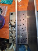
Andrew, something to look for is the alignment of the heatsink and chassis holes. My 400 S1, 400 S2, and 700 Pro all have the same machining error at the far right bottom output transistor location. This is easily fixed. Perhaps this is the source of your issue when snugging up the outputs. Below is a photo from my 700 Build thread. Look closely at the photo for the alignment mismatch that trashes the original socket and makes installing the WOAD backplane stepped washers a no go. Don't know if the 700 S1 suffers the same machining error, but needs looked at.
Attachments
AngrySailor
Veteran and General Yakker
- Joined
- Oct 15, 2014
- Messages
- 3,419
- Tagline
- ---not quite right
I’ll check that today. Thanks.
The days before laser precision (and QC)Andrew, something to look for is the alignment of the heatsink and chassis holes. My 400 S1, 400 S2, and 700 Pro all have the same machining error at the far right bottom output transistor location. This is easily fixed. Perhaps this is the source of your issue when snugging up the outputs. Below is a photo from my 700 Build thread. Look closely at the photo for the alignment mismatch that trashes the original socket and makes installing the WOAD backplane stepped washers a no go. Don't know if the 700 S1 suffers the same machining error, but needs looked at.
J!m
Veteran and General Yakker
I dare say that IS laser precision.
When actual machinists worked this stuff out, everything fit... correctly.
When actual machinists worked this stuff out, everything fit... correctly.
???I dare say that IS laser precision.
When actual machinists worked this stuff out, everything fit... correctly.
Skratch
Chief Journeyman
With today's technology there is no reason for misalignment
AngrySailor
Veteran and General Yakker
- Joined
- Oct 15, 2014
- Messages
- 3,419
- Tagline
- ---not quite right
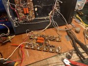
Kinda lazy day here. Fixed the parents furnace, needed a new circulation pump. Just soldered in Tim’s new bias resistors. Prob start putting eh backplane back in unless the urge to take a nap wins... still gotta change out them caps first be easier.
Attachments
- Joined
- Jan 14, 2011
- Messages
- 75,905
- Location
- Gillette, Wyo.
- Tagline
- Halfbiass...Electron Herder and Backass Woof
Yep...
AngrySailor
Veteran and General Yakker
- Joined
- Oct 15, 2014
- Messages
- 3,419
- Tagline
- ---not quite right
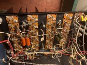
Back plane back into place with new bias resistors and Linda’s 0.33uF caps. Linda only had these caps on one channel... side note to anyone in the Niagara area, don’t use “Pete’s Electronics” what he doesn’t mess up he’ll steal (cough cough my RT-707 cough)...
Attachments
- Joined
- Jan 14, 2011
- Messages
- 75,905
- Location
- Gillette, Wyo.
- Tagline
- Halfbiass...Electron Herder and Backass Woof
Next time I'm there I'll be sure and heed that warning...
AngrySailor
Veteran and General Yakker
- Joined
- Oct 15, 2014
- Messages
- 3,419
- Tagline
- ---not quite right
Shit, are those bias resistors 2 watt??? Some reason I thought they were 1/4 watt and I got 1/2 watt as they had them in stock... fudge improbably gotta change them out eh?Next time I'm there I'll be sure and heed that warning...
- Joined
- Jan 14, 2011
- Messages
- 75,905
- Location
- Gillette, Wyo.
- Tagline
- Halfbiass...Electron Herder and Backass Woof
They'll work for troubleshooting..
AngrySailor
Veteran and General Yakker
- Joined
- Oct 15, 2014
- Messages
- 3,419
- Tagline
- ---not quite right
Ok, just installed the Phoenix connectors on runs board. What a pain to desolder the holes but I got it. I brushed the board when I built it with alcohol and a tooth brush but damn there’s still flux on it, you can see it better now that it yellowed some. Best way to clean it off? It’s hard as glass... what seminconductors did you want me to check Lee? Q7 & Q10 right? There was something else can remember where you posted it though...They'll work for troubleshooting..
- Joined
- Jan 14, 2011
- Messages
- 75,905
- Location
- Gillette, Wyo.
- Tagline
- Halfbiass...Electron Herder and Backass Woof
The diodes around those, the low voltage test points in the middle od the board. Rail fuses ok?
- Joined
- Jan 14, 2011
- Messages
- 75,905
- Location
- Gillette, Wyo.
- Tagline
- Halfbiass...Electron Herder and Backass Woof
For the really tough rosin----acetone. Dont get it on electrolytics.