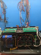
I just finished up a 400 with all of the goodies. Getting the transformer isolated was a challenge. I first tried heat shrink, which, to no surprise was too thick. I considered #12 screws and metric alternatives. While staring at the wall it hit me. Packing tape! The standard packing tape is a 1 7/8" wide. Here's the procedure.
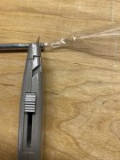
1. Take a piece of packing tape about 8" long and lay it down on a bench, adhesive side up. Make sure the cut end is square.
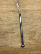
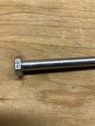
2. Lay the bolt down parallel to the tape with the head against the edge of the tape.
3. Carefully roll it up like a joint. No wrinkles.
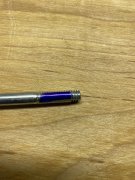
4. About 3/16" from the end use a knife to go around the bolt to cut the tape.
5. Grab the waste tape and pull it off the bolt.
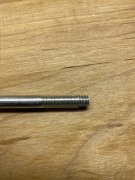
The image below with the blue Sharpie ink was done to show the end of the tape on the threads. You can not see the end of the tape next to the head, but it does go right up to the head.
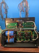
This technique provides about 3 layers of tape around the bolt. Before inserting the bolt in the transformer I pushed a 1/4" wooden dowel rod through the core to clean out any debris. If the tape is rolled up right it will go through with little resistance. Patience is a necessity. I had at least 10 failed attempts before all 4 bolts were wrapped. I used M8 nylon washers for isolation on each end of the bolt. I used flange nuts as seen in the last image.
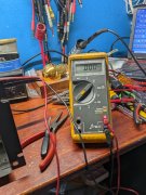
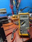
Resistance readings from the bolts to the chassis and core were infinite. I would liked to have done a hipot test of 500 volts or so but lacked a safe way to do it.
View attachment 59649
View attachment 59651
View attachment 59653
View attachment 59654
View attachment 59655
View attachment 59656
View attachment 59658


![IMG_3820[1].JPG](/data/attachments/56/56406-079ba9d4e4917d491e14db51e595d0fc.jpg)