- Joined
- Jan 14, 2011
- Messages
- 75,886
- Location
- Gillette, Wyo.
- Tagline
- Halfbiass...Electron Herder and Backass Woof
Thanks Joe. I guess I could have figured that out if I'd just RTFM!!

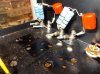
For those of you that receive a PL and the meters have moved--DO NOT PLUG THEM IN--THIS IS WHY!!
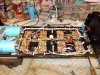
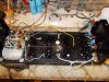
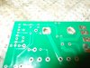
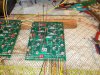
I decided on drilling out the DC protect board to facilitate using these connectors. It's a 2 sided board but it'll be in contact through the speaker posts so it'll remain conductive between top and bottom. One of my concerns was a resistor lead being awfully close to the nut. Turs out there's between 1/16--1/32 inch.
I decided on drilling out the DC protect board to facilitate using these connectors. It's a 2 sided board but it'll be in contact through the speaker posts so it'll remain conductive between top and bottom. One of my concerns was a resistor lead being awfully close to the nut. Turs out there's between 1/16--1/32 inch.
Just got back from AK, had to stir a little shit, heheheheheh....
The Pig made me do it..