Russ' Phase Linear 400 Ser I---TO BE WOPL'd

laatsch55

Administrator,
Staff member
Joined
Jan 14, 2011
Messages
75,594
Location
Gillette, Wyo.
Tagline
Halfbiass...Electron Herder and Backass Woof
Another CHERRY PL 400. Tried to test and get some "before" figures, wasn't going to happen. 80 volts DC on the right speaker outs. It's getting everything so no raeson to chase the boogeyman on this one.
 

Attachments

  • 100_3377.jpg
    100_3377.jpg
    95.8 KB · Views: 150
  • 100_3378.jpg
    100_3378.jpg
    86.1 KB · Views: 207
  • 100_3376.jpg
    100_3376.jpg
    94.9 KB · Views: 476
  • 100_3375.jpg
    100_3375.jpg
    91.6 KB · Views: 487
  • 100_3374.jpg
    100_3374.jpg
    81 KB · Views: 217
Another CHERRY PL 400. Tried to test and get some "before" figures, wasn't going to happen. 80 volts DC on the right speaker outs. It's getting everything so no raeson to chase the boogeyman on this one.

Everything, as in EVERYTHING Lee? Full comp?
 
This "full comp" has me intrigued. Spoke with Jer (had a few questions which he patiently tried to answer and I am thankful he could spare me the time) a little while ago and he explained what it is. I remember back in the day when point to point wiring was considered the trademark of highend (in fact it still is with boutique guitar heads) and circuit boards were used as a cost cutting measure. Seeing that the new boards are high grade and Jer explaining how it makes everything tight and reliable tells me that when I can, I will want this done with my 400 which has the Rev C board. I understand the Rev C cannot be used to full comp but Jer mentioned something about quasi comp whatever that is. In any event, I would want whatever is current and be waiting like everyone else for the next major breakthrough revision LMAO

Learning about this stuff and even reading threads like this have my head spinning. Measuring collectors and legs and whatever Q4s Q5s and everything else is so over my head. I wish I understood this stuff and I admire those who understand it and can talk converationally about it and the other person actually knows what to do/ It's damn fascinating to read and think about

If I was Michael, you guys would be exasperated and be just waiting for me to report that I am back safely from the hospital but sporting third degree burns and kinked hair
 
Last edited:
This "full comp" has me intrigued. Spoke with Jer (had a few questions which he patiently tried to answer and I am thankful he could spare me the time) a little while ago and he explained what it is. I remember back in the day when point to point wiring was considered the trademark of highend (in fact it still is with boutique guitar heads) and circuit boards were used as a cost cutting measure. Seeing that the new boards are high grade and Jer explaining how it makes everything tight and reliable tells me that when I can, I will want this done with my 400 which has the Rev C board. I understand the Rev C cannot be used to full comp but Jer mentioned something about quasi comp whatever that is. In any event, I would want whatever is current and be waiting like everyone else for the next major breakthrough revision LMAO

Learning about this stuff and even reading threads like this have my head spinning. Measuring collectors and legs and whatever Q4s Q5s and everything else is so over my head. I wish I understood this stuff and I admire those who understand it and can talk converationally about it and the other person actually knows what to do/ It's damn fascinating to read and think about

If I was Michael, you guys would be exasperated and be just waiting for me to report that I am back safely from the hospital but sporting third degree burns and kinked hair

(hehe... I'm going to answer here and hopefully I get it half right... here goes... )

In order to understand what fully complementary means to a PL amp, it's important to know "why" the PL's were not designed that way to begin with. Fully complementary essentially means that in your output section, the positive swing is handled by transistors of the NPN variety while the negative swing is handled with PNP devices. Manufacturing NPN devices with the required voltage and current characteristics was "barely" possible back in the early 70's, while PNP's were pretty much out of the question.

So PL used what is called a "quasi-complementary" design, where the positive swing was handled by NPN's just like true complementary, BUT.. the negative swing as well used NPN's. The devices on the negative side were basically "turned around" to where they would still conduct in the "correct" orientation, but where on the postive side the "emitter" leads were on the side of the speaker output, on the negative side the "collector"'s were tied to the speaker output instead of the same "emitter" leads. So in essence, "characteristics" on the negative swing are slightly different... but the overall design somehow compensates for this.

BUT.. now that we have devices out there, both NPN and PNP, that can handle the current and voltage on the PL's output section, we can go full (or "true") complementary using the PNP's on the negative half.. and with the "emitters" tied to the output since a PNP device "conducts" in an opposite fashion than NPN. End result is now both halfs are essentially "equal", therefore able to reproduce the output signal in an even "truer" fashion than the original design.

(tried to explain it and not get TOO complicated... Joe will probably correct me on a few points, heheh)

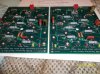
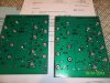
Now as far as the point to point versus PCB argument. One of the key disadvantages (and this is a prime suspect after our convo tonight) of the original design is the output transistor sockets. In a lot of cases, they're 30+ years old ... been through hell and back as far as heat.. moisture.. corrosion.. you name it. With Joe's backplane boards, we end up actually soldering them in. A good SOLID connection that will last for at least another 40 years. One can design a PCB with end cost in mind (as we know with the "dark ages" of the late 80's and 90's), but I'm pretty sure Joe didn't approach the design of the new PCB's that way. In fact, the new boards are designed with the intent of quality in mind - from heavy HEAVY copper runs "where it counts" to many other logical improvements over the original point to point. I've dealt with both... and these PCB's are definitely going to stand up better than the old point to point as time goes by.
 
These turned out a little better----
 

Attachments

  • 100_3382.jpg
    100_3382.jpg
    99.2 KB · Views: 145
  • 100_3381.jpg
    100_3381.jpg
    99.6 KB · Views: 134
  • 100_3380.jpg
    100_3380.jpg
    94.5 KB · Views: 126
  • 100_3379.jpg
    100_3379.jpg
    95.7 KB · Views: 133
  • 100_3378.jpg
    100_3378.jpg
    86.1 KB · Views: 111

If I was Michael, you guys would be exasperated and be just waiting for me to report that I am back safely from the hospital but sporting third degree burns and kinked hair


Wouldn't be the first time.....
 
Thanks Jer, been doing a little reading on NPN and PNP transistors and I see how they work opposite of eachother and it's all because of polarity

Am I wrong in thinking if the PL originally had two seperate power supplies, all one type could be used since they would not be fighting for supremacy in the same circuit? I see that a transistor either amplifies a signal or cuts it but what your telling me as that you need two types to balance and that is where I get lost. Seems to me that if an amp had seperate power supplies, each running their own channel, they would not be directly interacting and would not require a transistor fight to balance the same operation. This thought came up as a result of what I mentioned about how only one output fuse blows while the other is unblown BUT there is no signal output on the side with the unblown fuse. You mentioned they worked together so to me, it does not sound like a conventional two channel amp with independent channel fuses like I am used to... if one channel's fuse blows, the other channel is still playing

I am getting lost again, that blank feeling in the brain.... my left lobe is fighting with the right lobe like a PL LMAO
 
Last edited:
Thanks Joe, that's called redemption


HE"S GOIN IN FOLKS!!!!!!!!!!!!!
 

Attachments

  • 100_3383.jpg
    100_3383.jpg
    96.5 KB · Views: 75
Early Ser I. Made in Edmonds. Outputs out, faceplate off. Glad to see those wood screws gone!!!!
 

Attachments

  • 100_3388.jpg
    100_3388.jpg
    95.8 KB · Views: 89
  • 100_3387.jpg
    100_3387.jpg
    97.4 KB · Views: 81
  • 100_3385.jpg
    100_3385.jpg
    97.7 KB · Views: 91
  • 100_3386.jpg
    100_3386.jpg
    93.7 KB · Views: 76
  • 100_3384.jpg
    100_3384.jpg
    94.8 KB · Views: 79
I have a feeling Lee is laughing very hard right now while I keep refreshing the page hoping for an explanation I can wrap my head around. Right now, a bottle of aspirin would not kill this headache I am developing. I get this way when I am trying to learn something blind and hoping for the epiphany that explains it all and I can say WOW! What a stupid mofo I am for not understanding this in the first place

So, I keep refreshing... and refreshing and refreshing again. I think this is going to be a sleepless night for me
 
Last edited:
First time I've seen C11,C15, C16 stood up

In photo 4, is that what you are referring to standing up? The two caps soldered together with that green thingy attached and the other cap standing up (rightside of image)
 
C3 is a 22uf at 100. It had Q9 in the left channel replaced with a Texas Instruments, originals were Etco's. Q1, Q2 2N5401's---- Q3,Q4----MPSA5172's.
 
No Ron. On the main board shot, the blue electrolytic caps on their end.
 
Ron, I'm not laughing. I was there where you are 5 years ago.
 
C3 is a 22uf at 100. It had Q9 in the left channel replaced with a Texas Instruments, originals were Etco's. Q1, Q2 2N5401's---- Q3,Q4----MPSA5172's.

Hoping the 5401s and 5172s were the other way around Lee...
 
Back
Top