I ended up setting the output gain to -6 db on the C-1 btw
The RCA plates are scarce these days. I bought the last 3 from AJ and I only got 1 left. I have the drawing for it and I was thinking that instead of having them made of the heavy aluminum, I was going to scan it into the PCB site I use and have some spun up out of PCB material (they also make the pcb's out of aluminum but don't know the cost yet). Having them built by a machine shop is going to be too expensive. If I use the board house, I could try and have Plated through holes where the RCA's go through to toughen them up. ???? Just thinkin out loud.
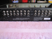
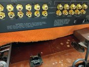
Speaking of doing the RCA mod, I had a customer send me their C1 for some upgrades a couple months ago and I did the RCA mod on it (among other things) and had to do some repairs just to test it before I started working on it. Well, it turned out nice and tested quiet as a mouse, and when I shipped it back, I got a couple rude comments about the Red and Black RCA's I installed and the person said "It's common practice to use Red and White RCA's so you don't get them mixed up"!!!! Well, the chinee dude I use for my RCA source (26 per C1) only has red and black so that's what I use. The red and black bands on the jacks are just little rubber bands so I told the person to take the black rubbers off, go to hobby lobby and get a REAL small paint brush and a small bottle of white paint put the jacks in the drill and as it spins, paint the recessed area where the black band was, and put a couple coats on and wipe any drunk slippage off. Well customer was upset and then I showed the pic of the back of his unit that was sent to me and I said "What the Fuck, this is how buffalo Bob makes them" NO COLOR ON ANY RCA, see pic below. Never heard back from the person. If you have a special request on color, size, material etc.... Put it in your request for service, I will bend over backwards to try and accommodate my customers with green knobs, pink face plates pretty much whatever they want (or if they are brave and let me decide, you never know what I'll come up with but some people are just miserable and want YOU to be the same way..... Fuck that..... Anyway, I had a customer local wanted his C-1 done too so I took the black rubber bands off, and put the rca's in the chuck and painted the recess which Looked nice but thats several extra hours of work so I have to charge for it now. I did this one for nothing extra just to try my own suggestion. I had a whole list of shit to fix before I could work on the rude customers C1. The metal caps fell off all the knobs (extra time to fix them), most of the screw holes were stripped out, hardware missing, the whole unit looked like it was rode hard and put away wet. How's about you clean your shit before shipping and make a list for me telling me what condition it's in so I can utilize my time more efficiently???????????????????? I have to test it before and after to show our upgrades/mods do as expected. If it shows up broke dick, and I need to fix it first, then somethings got to give........ OK, enough said. If I get a free minute, I'll see if I can upload the drawing at the board house and see what Wun Hung Lo is going to charge me, maybe we can do a group grope Kyle since it's cheaper by the dozen.

I'm just about finished with a local C1 and the RCA plate looks fine and he can see the R and the L on the back so I didn't have to paint shit.


