And the journey begins...

MarkWComer

Veteran and General Yakker
Joined
Nov 1, 2014
Messages
3,493
Location
Gaston, SC
Tagline
Victim of the record bug since age five
#21
You elevated a few caps above the board. Not wrong, but unusual. I assume for heat dissipation? I elevated the high wattage resistors a bit on my builds for this reason because of the obvious heat damage on the original control circuits. This may be moot, did it regardless. I think I did this on the emitter resistors as well, don’t recall precisely.
 
Joined
May 17, 2023
Messages
306
Location
Finland via the deep south
Tagline
Details, details
#22
You elevated a few caps above the board. Not wrong, but unusual. I assume for heat dissipation? I elevated the high wattage resistors a bit on my builds for this reason because of the obvious heat damage on the original control circuits. This may be moot, did it regardless. I think I did this on the emitter resistors as well, don’t recall precisely.
I was just copying what was shown in the recommended assembly instructions I got from Joe.
1698499535880.png I did it partially so I would put a little distance from the solder joint to the device...I tend to err on the cautious side
 

MarkWComer

Veteran and General Yakker
Joined
Nov 1, 2014
Messages
3,493
Location
Gaston, SC
Tagline
Victim of the record bug since age five
#23
I was just copying what was shown in the recommended assembly instructions I got from Joe.
View attachment 78043 I did it partially so I would put a little distance from the solder joint to the device...I tend to err on the cautious side
Things have changed a bit since my last build. I just thought it was unusual. I know the backplanes have been revised since then, tempted to renovate, but I know that what I have is far superior to most of what’s available on the market these days. I really like that rectifier snubber board- what a great idea!

Wishing you great success on your build!
 
Joined
May 17, 2023
Messages
306
Location
Finland via the deep south
Tagline
Details, details
#24
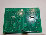
You missed 2 solder joints on the bottom of the control PCB (circled in Red). You apparently placed the -15V test point and did not solder.

Post a second picture of the control board after you thoroughly clean and inspect for solder balls and debris.

I wish I could say that I left those unsoldered on purpose to see if anybody was really looking and you won the prize for attention to detail but damn, good catch! (you get the prize for attention to detail anyway!!!)

You are right, I put all of the test points in and only soldered "most" of them...And in the next picture you see all of the screw heads will be properly aligned :cool:
 

Hexis22

Chief Journeyman
Joined
Dec 28, 2022
Messages
677
Location
Wisconsin
#25
You are right, I put all of the test points in and only soldered "most" of them...And in the next picture you see all of the screw heads will be properly aligned :cool:
Good to see you're reviewing past build threads...

You will not find a more attentive and critical group than the members of this forum!
 

Gepetto

Administrator
Staff member
Joined
May 15, 2011
Messages
13,944
Location
Sterling, MA
Tagline
Old 'Arn Enthusiast
#26
You elevated a few caps above the board. Not wrong, but unusual. I assume for heat dissipation? I elevated the high wattage resistors a bit on my builds for this reason because of the obvious heat damage on the original control circuits. This may be moot, did it regardless. I think I did this on the emitter resistors as well, don’t recall precisely.
Hi Mark
The dipped mica caps have epoxy coating that sometimes extends in a very thin coating down the wire lead. The lead with coating will fit in the hole in the PCB leading to what you think is a good solder connection, but isn't. Raising the mica caps enough to avoid this is important. I always test solder from the top side of the lead first on these and then solder the bottom of the lead to ensure a proper solder joint. These caps are critical to proper operation and stability of the amp.
 

Gepetto

Administrator
Staff member
Joined
May 15, 2011
Messages
13,944
Location
Sterling, MA
Tagline
Old 'Arn Enthusiast
#27
Here is the instruction on the Bill of Material...

9 Populate and solder in the mica and film caps next (leave large electrolytics for the last step). Position film caps with bottom flush to the board. Mica caps should be spaced off of board slightly showing bare lead above the topside of the PC board to prevent the conformal coating from entering the PCB hole. Solder and trim as above.
 

MarkWComer

Veteran and General Yakker
Joined
Nov 1, 2014
Messages
3,493
Location
Gaston, SC
Tagline
Victim of the record bug since age five
#28
Hi Mark
The dipped mica caps have epoxy coating that sometimes extends in a very thin coating down the wire lead. The lead with coating will fit in the hole in the PCB leading to what you think is a good solder connection, but isn't. Raising the mica caps enough to avoid this is important. I always test solder from the top side of the lead first on these and then solder the bottom of the lead to ensure a proper solder joint. These caps are critical to proper operation and stability of the amp.
Thanks- glad you told me that!
 
Joined
May 17, 2023
Messages
306
Location
Finland via the deep south
Tagline
Details, details
#29
Here is the instruction on the Bill of Material...

9 Populate and solder in the mica and film caps next (leave large electrolytics for the last step). Position film caps with bottom flush to the board. Mica caps should be spaced off of board slightly showing bare lead above the topside of the PC board to prevent the conformal coating from entering the PCB hole. Solder and trim as above.
Joe,

I still haven't found this BOM that you refer to...and is there some sort of narrative that goes along with the assembly slide show?
 
Joined
May 17, 2023
Messages
306
Location
Finland via the deep south
Tagline
Details, details
#33
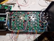
Got the first snow today so I got a few bits and bobs soldered in.
20231030_205839.jpg

The alcohol I was using for cleaning had some friggin' surfactant or something in it and left a film on the board...got some 99,9% isopropyl on the way, should be here next week (the joys of living in the middle of nowhere) so can do a proper cleaning of the board. (was thinking about getting an ultrasonic cleaner, that would really do the job) 20231030_205948.jpg

Now it's time to start with the chassis and power supply work. I have been thinking a lot about finding the "quiet" primary lead but unfortunately over here although you have the ISO chassis plug the 220V plug allows you to go either way so unless I put a "reverse polarity" light between the unused ground in the ISO to the "neutral"...does it really make that much difference? If it does, I will put in the light :cool:

And speaking of transformer work, I take it the transformer isolation exercise is to electrically isolate the transformer from the chassis, is this correct? If so, what do you do about making sure you don't get contact between the chassis and transformer housing or does the bushing space it far enough away that you don't have to worry about it? (I haven't mocked it up yet so I haven't "seen" the situation and the pictures in Eric's thread aren't clear enough to tell) Just trying to work out the details beforehand so I don't have a lot of "on the fly" modifications...

I'll leave you with just a little something to remind us of summer now that old man winter is rapidly approaching...

473747092_0d6b7c1f3b.jpg
 

Hexis22

Chief Journeyman
Joined
Dec 28, 2022
Messages
677
Location
Wisconsin
#34
You just need to isolate the transformer bolts from chassis ground using bushings.

I would not call either the bolt isolation or preferred primary connection orientation a
“must have”, both are additional levels of refinements in the quest for lowering the noise floor.

It’s up to you how far to take the project.
 

MarkWComer

Veteran and General Yakker
Joined
Nov 1, 2014
Messages
3,493
Location
Gaston, SC
Tagline
Victim of the record bug since age five
#35
And speaking of transformer work, I take it the transformer isolation exercise is to electrically isolate the transformer from the chassis, is this correct? If so, what do you do about making sure you don't get contact between the chassis and transformer housing or does the bushing space it far enough away that you don't have to worry about it?

View attachment 78093
I used heat shrink tube on the transformer bolts. Some others have used plastic drinking straws. And of course, nylon washers on the bolts at both ends.
 
Joined
May 17, 2023
Messages
306
Location
Finland via the deep south
Tagline
Details, details
#36
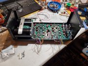
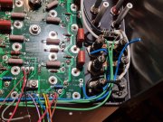
Made a little progress today, mostly mechanical work, test fitting things to work on wire routing...Still need to get/make the bushings for the transformer bolts, clean the boards, prep the heat sinks and then I can start with "real" final assembly.

20231031_234510.jpg

20231031_234650.jpg

20231031_234536.jpg

20231031_234628.jpg

Well, winter is here, might as well enjoy it...
wtf-girl-photo-a-long-way-home.jpg
 

MarkWComer

Veteran and General Yakker
Joined
Nov 1, 2014
Messages
3,493
Location
Gaston, SC
Tagline
Victim of the record bug since age five
#37
Changes have been made since my last build. Picofuses are gone, replaced with AGX.
So what’s that little hoojit between the backplanes?
 

Gepetto

Administrator
Staff member
Joined
May 15, 2011
Messages
13,944
Location
Sterling, MA
Tagline
Old 'Arn Enthusiast
#39
Made a little progress today, mostly mechanical work, test fitting things to work on wire routing...Still need to get/make the bushings for the transformer bolts, clean the boards, prep the heat sinks and then I can start with "real" final assembly.

View attachment 78102

View attachment 78104

View attachment 78103

View attachment 78105

Well, winter is here, might as well enjoy it...
View attachment 78106
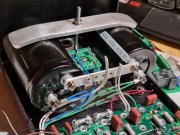
Hi Robbie, you may want to check the ring lugs supporting the green and blue wires on the bulk caps. The solder joint looks cold on both. You were probably focused on the girl in the snow at the time :)
 
Joined
May 17, 2023
Messages
306
Location
Finland via the deep south
Tagline
Details, details
#40
Hi Robbie, you may want to check the ring lugs supporting the green and blue wires on the bulk caps. The solder joint looks cold on both. You were probably focused on the girl in the snow at the time :)
I'll go back and touch both of them up but they were good and hot, solder just melted like crazy when it touched the fitting (even though I had the iron mostly on the wire) but just in case...
 
Top