well, i had the dcprotect board wired wrong...
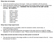
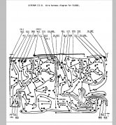
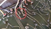
the directions in the 400 relay install pdf had the white wire in j1-1
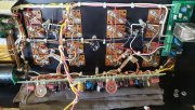
View attachment 65282
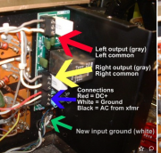
flicker had the gray wire in j1-1
so, that would explain the dc on the outputs....
View attachment 65283
i did not do enough research before i installed it...i should have checked both places....
and i thought how difficult can this be....i took too much for granted....
anyway...
i have removed all transistors including the drivers....all tested good...
i marked them and put the left channel drivers on the right channel and the right driver on the left channel...
with a row of 909s above this...which i was advised this was enough to start checking....
no change....
can set bias on the left channel and can not set the right channel...
and the dc protect does not engage...
so the offset of course shows zero....
i even tried without the screws just to be sure i was not shorting thru a sil pad or with a screw...
no difference...
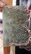
i guess there has to be something on the driver board holding it down....
i checked the voltages on the dcp board
using chassis ground...for the negative lead on the dvm
j1 1 is -79v dc
j1 3 is 0
j2 1 is 64v dc
j2 3 is 0
j3 1 65v dc
j3 2 is 0
j3 3 is 60v ac...
i am pretty sure j1 1 is not what it is supposed to be....
what a bucket of worms this has turned out to be...lol
such is life...
thanks in advance for any advice....

