Hold on.Okay, so at the moment I have + at the very top (for both caps) and - at the bottom. You're saying it's supposed to be the other way? Negative at the top?
So, rotate the caps 180 and them switch/swap the wires from the bridge rectifier. Correct?

You are using an out of date browser. It may not display this or other websites correctly.
You should upgrade or use an alternative browser.
You should upgrade or use an alternative browser.
phase linear 400
- Thread starter gene french
- Start date
Have to get off my iPhone to a real computerHold on.
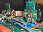
OK now on a real computer. The bulk caps are in the right order, sorry about that. However the Bridge - terminal is wired to the B+ cap at the top and the Bridge + terminal is wired to the B-cap at the bottom of the amp. The wiring from the bridge to the bulk cap is incorrect and reverse biasing the bulk caps which is why you DBT stays bright. Your bridge mounting is 180 degrees rotated from the normal bridge rotation. Bridge + terminal is usually in the Northeast quadrant.Have to get off my iPhone to a real computer
ABebar
Journeyman
ABebar
Journeyman
Awesome. That's an easy fix. Let me swap and report back. Thank you so much for the prompt response!OK now on a real computer. The bulk caps are in the right order, sorry about that. However the Bridge - terminal is wired to the B+ cap at the top and the Bridge + terminal is wired to the B-cap at the bottom of the amp. The wiring from the bridge to the bulk cap is incorrect and reverse biasing the bulk caps which is why you DBT stays bright. Your bridge mounting is 180 degrees rotated from the normal bridge rotation. Bridge + terminal is usually in the Northeast quadrant.
Like this

ABebar
Journeyman
Got it. Reworking now. Thank you again!Like this
View attachment 64200
ABebar
Journeyman
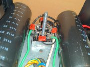
Alright. Rectifier rotated. About to retry startup procedure. Btw, the instructions say "check all voltages for proper values." I was planning to check b+ and b-. Are there any other critical checks before moving forward to adding the lower row of output transistors?
Attachments
Vintage 700b
Chief Journeyman
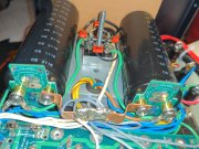
There is an awful lot of flux residue on these newly soldered connections.
This spells trouble down the road. I seem to put in 3X the time cleaning as I do actually soldering get them clean enough.
That is a hard lesson learned fast.
This spells trouble down the road. I seem to put in 3X the time cleaning as I do actually soldering get them clean enough.
That is a hard lesson learned fast.
ABebar
Journeyman
Woohoo! DBT check passed! I have +/-85vdc on both rails. Ready to add in fuses and the bottom row. Wish me luck!
ABebar
Journeyman
My boards are clean, but I don't spend near the same amount of time on point to point cleanliness. Besides taking pride in ones work, what's the risk?There is an awful lot of flux residue on these newly soldered connections.
This spells trouble down the road. I seem to put in 3X the time cleaning as I do actually soldering get them clean enough.
That is a hard lesson learned fast.
WOPL Sniffer
Veteran and General Yakker
There is an awful lot of flux residue on these newly soldered connections.
This spells trouble down the road. I seem to put in 3X the time cleaning as I do actually soldering get them clean enough.
That is a hard lesson learned fast.
Yep, solder balls and flux will ruin a good day quick.
Vintage 700b
Chief Journeyman
My boards are clean, but I don't spend near the same amount of time on point to point cleanliness. Besides taking pride in ones work, what's the risk?
The chemistry of the flux residue is highly acidic. As time goes on, that flux residue combines with atmospheric moisture (heating/cooling cycles) and I have seen it raise traces, or corrode joints. The flux residue is semi-permeable, and will hold moisture, which eats away all of the hard work you have done getting your connection just right. It’s just cheap insurance to finish the job…. pay me now, or really pay me later. It’s just what I do. I hate reworking poorly cleaned boards and connections when I open up a new piece of equipment, see it too often.
ABebar
Journeyman
The dreaded dentritic growth?
Good point. I'll take the cheap (free) insurance and clean up the bridge and fused connections.
Good point. I'll take the cheap (free) insurance and clean up the bridge and fused connections.
Vintage 700b
Chief Journeyman
Yes, exactly.
The dreaded dentritic growth?
Good point. I'll take the cheap (free) insurance and clean up the bridge and fused connections.
Adam, make sure your solder joints at the bridge are not cold. A couple of them look sketchy where the solder is not flowing into a meniscus on the bridge tab, rather it is a blob sitting on top of the tab. Very high peak currents exist at these connection points. Trying not to be critical but these should be improved up. You will need to leave your iron dwell on these connection points longer to fully heat the tab and let the solder flow. These tabs are designed primarily for Faston connections. When soldering, you have to overcome the thermal mass that exists here.
Yahoo!Woohoo! DBT check passed! I have +/-85vdc on both rails. Ready to add in fuses and the bottom row. Wish me luck!
gene french
Veteran and General Yakker
- Joined
- Mar 6, 2022
- Messages
- 5,884
- Tagline
- music...the healer of souls...
congratulations!!!!!
By the way, that's a dual primary Series 2 transformer. In your post this morning you said 400 Series 1 amp. Most probably not the original transformer. Not a issue but thought I'd mention it. Glad your making progress!Alright. Rectifier rotated. About to retry startup procedure. Btw, the instructions say "check all voltages for proper values." I was planning to check b+ and b-. Are there any other critical checks before moving forward to adding the lower row of output transistors?
ABebar
Journeyman
Good to know! I bought this 400s1, 10 (yes, ten) 700b's, and two 700s2's from a theater in San Francisco that closed because of the pandemic. They have been worked and reworked extensively. Some are in bad enough condition where they will be stripped for parts, but I'm hoping to end up with 4 or 5 WOPL's and a few rebuilt stock amps out of the best parts. This is the first of many for me.By the way, that's a dual primary Series 2 transformer. In your post this morning you said 400 Series 1 amp. Most probably not the original transformer. Not a issue but thought I'd mention it. Glad your making progress!